Small versus Large Utility Boilers
The utility or power boilers are of two types:
1. Small utility boilers ranging from 100 MW (400 tph) to 300 MW (—1000 tph)
2. Large utility boilers >300 MW (—1000 tph)
A size of 1000 tph is arbitrary; the dividing line between small and large utility boilers of 400 tph is for industrial and utility boilers.
Small utility boilers are conventional drum-type single reheat PF-fired boilers operating at high pressures (HPs) and high temperatures on mostly natural or assisted circulation. Large utility boilers, by their size, can accommodate certain advanced features:
• Once-through system
• Supercritical (SC) steam parameters
• Variable pressure operation
• Double reheat at >800 MW
Large utility boilers can also be conventional drum-type natural or assisted-circulation boilers when they are used for mainly base load operation. They have been used for sliding pressure and two-shift operation, but SC boilers are more suited and offer greater flexibility.
Utility boilers represent the most advanced type. The working conditions to which they are subjected are the most arduous. The expectations from the modern utility boilers can be summarized in the following manner:
• Highest efficiency with lowest fuel consumption
• Flexibility to burn a range of coals with differing fouling characteristics
• Highest availability
• Short start-up time
• Quick load following capability
Several measures may be taken in a power cycle design to increase the efficiency of a plant.
• Increasing the main steam pressure
• Increasing SH and RH steam temperatures
• Adopting double RH
• Reducing flue gas-exit temperature
• Increasing feed water (FW) temperature
• Reducing condenser pressure
At drum pressure of —200 bar and SH/RH temperature of 540/565°C, limits are reached in natural circulation drum-type boilers in respect of steam pressures and temperatures with plant thermal efficiency reaching 42% on NCV and 40% on GCV. With the limits for the flue gas exit temperatures and unburnt losses reached long ago, the next improvement could come only by adopting SC conditions. It must be clarified that the SC conditions do not increase the boiler efficiency per se, as the efficiency is governed by stack losses and unburnt losses, neither of which is affected by the steam pressure adopted. The higher steaming conditions basically increase the overall steam cycle efficiency. There is, correspondingly, a reduction in the fuel input that also reduces the CO2 generation and sizing of auxiliaries such as the fans and pumps on per megawatt basis.
Adopting SC is a major step, as it involves extensive changes in the way the boiler and turbine are built. There are changes to steam piping, controls, and other auxiliaries such as boiler fed pumps (BFPs), and so on.
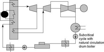
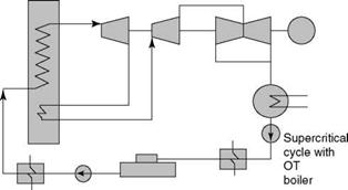
The subcritical and SC steam cycles are depicted in Figure 9.9 and also in Figure 9.10. (RH is not depicted here for the sake of simplicity.) The difference is in the higher operating cycle pressure, leading to higher cycle efficiency. For the same heat loss in a condenser more work is done in a boiler and a turbine and hence the efficiency is higher. The boiler construction is different, in that there is no longer a drum.
|
FIGURE 9.9 Sub — and supercritical cycles on T-s chart. |
|
|
|
|
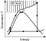
|
Subcritical cycle Supercritical cycle |
![]() FIGURE 9.10
FIGURE 9.10
Sub — and supercritical cycles.
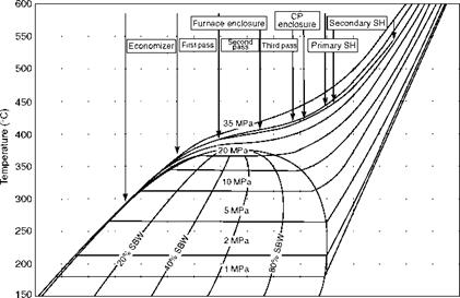
Figure 9.11 depicts the steam condition of a typical 1300 MW SC boiler on a T-s diagram. Subcooled water entering the economizer (ECON) goes directly to SH as the pressure is above the critical pressure bypassing the evaporation zone.
Progress of Supercritical Boilers
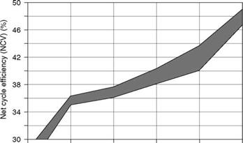
Figure 9.12 traces the rise in plant efficiencies on NCV over the years. Efficiencies beyond —42% on NCV are achieved only by adopting SC conditions. Plant efficiency increases
|
600 800 1000 1200 1400 1600 1800 2000 2200 2400 2600 2800 3000 3200 3400 3600 3800 Enthalpy (kJ/kg) FIGURE 9.11 Typical steam cycle of 1300 MW supercritical boiler on T-s diagram. (From Babcock and Wilcox Company, U. S.A. With permission.) |
|
1950 1960 1970 1980 1990 2000 Commissioning year |
FIGURE 9.12
Rise in plant efficiency over time.
From 42 to 45% over a decade and a half were realized by the increase in steam temperature from 540/540 to 600/620°C (~1005-1110/1150°F) and pressure from 200 to —310 bar (2900-4500 psia) along with double reheating. Another —30% points is achievable as the cycle conditions climb to 350 bar, 700/720°C (—5000 psig/1300/1300°F) called thermie or AD 700 conditions.
Supercritical and Ultra Supercritical Boilers
Supercritical condition, as per ASME steam tables, is at
• 220.7 bar and 374.1°C (3200.1 psia and 705.1°F) when water progressively converts to steam without boiling and with no latent heat addition. These figures can vary slightly, depending on the steam tables followed, but the variance is inconsequential for practical purposes.
• Supercritical boilers operate up to —240 bar (3500 psi nominal).
• Ultra SC (USC) boilers operate at —310 bar (4500 psi nominal) or higher.
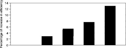
The overall cycle efficiency increases as the pressure and temperature are increased (Figure 9.13). The rise is depicted over the base case of drum-type boiler operating at subcritical steaming conditions, which can be taken as 42% on NCV and 40% on GCV. Boilers up to 315 bar and 600/620°C (—4500 psia/1110/1150°F) are in operation, while those up to 350 bar and 700/720°C (—5000 psia/1300/1330°F) are in the planning stage. RH temperature can be —15 to 20°C higher than the main steam temperature, as the RH pressure is much lower at about one-fourth of the main steam pressure, which permits higher RH temperature for the same stress levels. Or a lower metallurgy can be used for RH tubes without increasing the RH temperature, which is rarely practiced. Often SHOT and RHOT are maintained at the same level.
Figure 9.13 depicts the progress of high-temperature metallurgy.
Improvement of Supercritical Boilers over Drum Boilers
• Fuel savings due to higher cycle efficiency and hence reduced operating costs
• Reduction of CO2 emissions due to lower fuel input for the same power
• Superior load dynamics as the thick-walled components are avoided and there is no water in circulation
• Part load performance improves with variable/sliding pressure operation
• No blowdown
|
|
|
538°C |
540°C |
585°C |
620°C |
700°C |
|
538°C |
570°C |
600°C |
620°C |
720°C |
|
175 Bar |
250 Bar |
270 Bar |
315 Bar |
350 Bar |
|
T 22 |
X 20 |
T 91 |
Austenite |
Inconel |
FIGURE 9.13
Rise in cycle efficiency as steaming conditions improve.
Fuel Savings
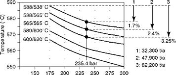
For a typical 500 MW unit, the savings in coal consumption and improvement in efficiency are depicted in Figure 9.14 and Table 9.3, taken from the in-house technical articles of the Steinmueller GmbH, as was Figure 9.13.
• This is based on operating the plant at 6500 h/year with a high-ash coal having an NCV of 3330 kcal/kg.
• The improvement in cycle efficiency is 1.7, 2.4, and 3.25% points, over the base case (option 1) with steaming conditions of 175 bar and 538/538°C (2500 psig/1000/ 1000°F) conditions, which is significant.
• This is at a pressure level of 235.4 bar (3400 psig), which can increase at higher pressure and temperature.
• The boiler efficiency under all conditions remains the same, but both the main steam and RH flow reduce with increase in pressure due to higher cycle efficiency.
Carbon Dioxide Reduction
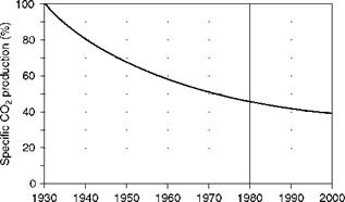
As there is a reduction in the coal consumption, the total CO2 from the plant reduces by the same amount. This makes the SC boilers effective for clean coal technology. Figure 9.15 illustrates the steady reduction in specific CO2 production from power plants over the years.
|
Specific coal consumption (kg/MWh) Coal saving
Main steam pressure (bar) |
|
FIGURE 9.14 Effect of increased steaming conditions on fuel consumption. TABLE 9.3 Options for SC Conditions for 500 MW Unit
|
Better Load Dynamics
Besides being more efficient, SC boilers are also more dynamically responsive as the
• Thermal inertia is much lower due to the absence of circulating water.
• The separator and water level vessels replace the thick-walled drum.
|
FIGURE 9.16 Load transients in drum and once-through boilers. |
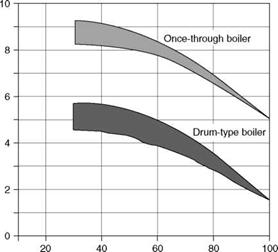
![]() These vessels come into picture for subcritical part load operation. At SC operation, however, they act like headers. Figure 9.16 brings out the differences in the response of the two systems. Table 9.4 tabulates the weights of the heavy components in two similar-sized boilers to depict the vast difference between the NC and SC boilers. The weights and dimensions are merely indicative.
These vessels come into picture for subcritical part load operation. At SC operation, however, they act like headers. Figure 9.16 brings out the differences in the response of the two systems. Table 9.4 tabulates the weights of the heavy components in two similar-sized boilers to depict the vast difference between the NC and SC boilers. The weights and dimensions are merely indicative.
|
Year FIGURE 9.15 Reduction in specific CO2 generation, 1930-2000. |
|
Load rate (% MCR) |
TABLE 9.4
Comparison of Thick-Walled Vessels in Drum and SC Boilers
|
660 MW |
![]()
|
720 MW |
![]() Parameter
Parameter
Type
Component
Size (0 X t X L) (mm)
Weight (Te)
NC
Drum
2,210 X 150 X 33,000 355
SC
Separator vessel 720 X 66 X 3500 24
Water level vessel 585 X 60 X 19,900 22
|
|
|
240 210 180 150 120 90 60 30 0 |
|
<1 8 Time after shutdown (h) |
|
48 |
FIGURE 9.17
Typical hot, warm, and cold start-up times.
The result of the thick PPs is a slower load response of drum-type boilers as compared to OT boilers working at either subcritical or SC pressures. The comparison in Figure 9.16 considers the OT boiler with sliding pressure operation.
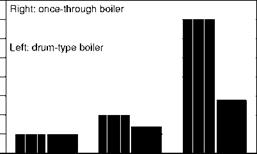
The time taken for hot, warm, and cold starts is another important parameter in measuring the boiler dynamics. On hot starts there may be no perceptible difference, but on cold starts the drum boilers are good deal slower as shown in the accompanying bar graph (Figure 9.17).
Variable/Sliding Pressure Operation
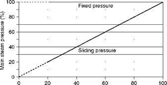
What is variable pressure operation? Steam generation at SC conditions ensures high efficiency at full load, but it must be complemented by variable or sliding pressure operation to obtain good part load efficiency and dynamics. A steam turbine demands lower inlet pressures at lower loads. Generally, conventional drum-type boilers generate steam at a constant pressure, which is then reduced in the main throttle valves to feed the nozzles at a suitable lower pressure. This is not always the case and drum-type boilers are also designed for variable pressure operation, particularly with the help of assisted circulation. A modified sliding pressure is also adopted where SOP is held constant up to a load and allowed to elide, taking an intermediate position. See Figure 9.18. With fixed SOP the drop in the throttle valve is, thus, a waste of energy, which increases as the load reduces. A more efficient system would generate steam at lower variable pressures instead of generating steam at a higher pressure and killing in the throttle valves. The throttle valves and the main stop valves could be dispensed with, and the speed of the feed pump could be varied to suit the inlet pressure of the turbine. This is called the variable pressure operation.
|
Load (%) |
|
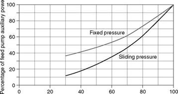
Load (%) FIGURE 9.19 Auxiliary power of boiler feed pumps in fixed and sliding operations. |
|
FIGURE 9.18 Variable and sliding pressure operation. |
![]() Why are the drum-type boilers not so well suited for variable pressure? The sudden pressure variations promote
Why are the drum-type boilers not so well suited for variable pressure? The sudden pressure variations promote
• Steam formation in the downcomers during load dips, which causes instability of circulation
• Disturbances to the water surface in the drum, affecting the controls
• Differential temperatures between the top and bottom of the drum, creating serious thermal stresses due to the thickness of the drum
Once-through boilers, both subcritical and SC, with no drums are ideal for variable or sliding pressure operation, which has the following main advantages:
• The turbine efficiency is higher as there is no throttling loss.
• Auxiliary power consumption of BFP is lower as the pump has to work against lower head at all loads. The savings increase for part loads (Figure 9.19).
• All pressure components are at lower pressure and hence are subject to reduced stress levels.
No Blowdown
Once-through boilers do not require blowdown as all the water gets converted to steam. This is an advantage as the makeup water quantity reduces. At the same time the water quality requirements are stringent for OT boilers with nothing less than condensate polishing systems of high reliability.
Of the several designs in operation, essentially three types and their variants can be considered in the utility market for coal and lignite, the main fuels. Oil — and gas-fired boilers for utilities are no longer considered. The boiler types are
• Two-pass boilers
• Single-pass or tower-type boilers
• Down shot boilers—V or W type
The nomenclature is based on the numbers or shapes of gas passes in the boiler.
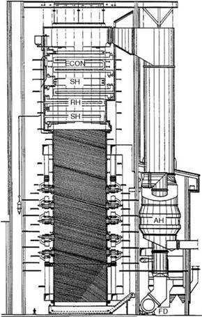
Two-pass boilers shown in Figures 9.20 and 9.21 are common and have progressed from smaller sizes in the same form. The main advantages are as follows:
• Two-pass boilers are not so tall and erection is easier.
• The boilers are usually supported on six columns and hence the structure can be a little lighter.
• The support elements for the vertical surfaces are located above the furnace roof outside the gas flow and protected from the erosive forces of the gases.
• The SH and RH are suspended from the roof and are free to expand downward.
• The roof is made of SH tubes, which minimizes the relative expansion of the SH and RH tubes as they penetrate the roof. Gas leakage is minimal.
• Widely spaced radiant sections in platens and panels and steam-cooled walls in the furnace have high heat absorption that increases the temperature control range.
The main drawbacks of the two-pass design are that
• The SH and at times the RH are not drainable, requiring longer start-up times and greater care during start-up.
• There are gas turns over the convection banks when flue gases travel toward the second pass, making them vulnerable to tube erosion both in the interpass area and in the first set of tubes of the second pass.
Drainable SHs are very beneficial as they
• Can be fully drained and, therefore, impose no limitation on the inlet gas temperature during start-up. In the nondrainable SH, the condensed steam residing in the tubes requires a gentle heating so that the steam formed finds its way out and does not create vapor locking that leads to tube overheating and increases the start-up time.
• Are easy to preserve during long layoffs as dry preservation can be adopted. In cold climates this is beneficial as there is no risk of freezing.
|
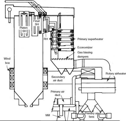
FIGURE 9.20 Two-pass opposed wall-fired boiler with divided gas flow in second pass and part vertical superheater and reheater. |
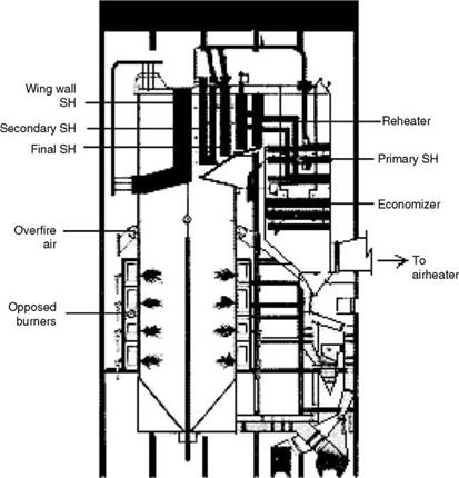
In the arrangement shown in Figure 9.21, with no division in the second pass, the RH temperature is controlled by the burner tilt of the corner firing system and the SH temperature by the spray water. If wall firing is employed in place of the corner firing, it is common to have two parallel paths in the second pass for SH and RH coils independently. This is also called divided convection pass and is shown in Figure 9.20. Control dampers at the end of each path regulate the temperatures by proportioning the gas flow.
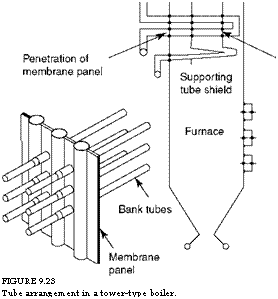
Tower-type boilers are shown in Figure 9.22. All the convective surfaces are horizontal and are stacked one above the other to prevent any gas turns over them. The horizontal surfaces are fully drainable, making the design amenable to better dynamics. All the flue gases flow normal to the convective surfaces and hence the erosion tendencies are greatly reduced. Figure 9.23 shows the method of supporting SH sections on the screen tubes and the walls. However, the gas velocity limits are to be respected. The cooled gases at the ECON exit come out of the first pass to get further cooled in the AH. The tower-type boilers are —25% taller but occupy some 20% less floor area.
|
FIGURE 9.21 Two-pass opposed fired boiler with single second pass with part vertical and part horizontal superheater and reheater. |
Tower-type boilers have the following advantages:
• There are no gas turns on the convective surfaces, making them safe from erosion.
• All the convective surfaces are horizontal and hence drainable, permitting faster start-up and shutdown.
• They are supported on four main columns, making the arrangement very clean and elegant.
The tower-type boilers have the following drawbacks:
• They are difficult to erect, but the accessibility largely reduces the erection complications.
• The supporting tubes and elements are in the gas path, exposing them to the erosive forces and high temperatures. The start-up time is limited by the temperature attained by the support tubes.
• The radiant heat available to the SH and the RH is limited, and more surface is required to achieve the same turndown.
|
FIGURE 9.22 Tower-type supercritical boiler with opposed firing and horizontal drainable superheater and reheater. |
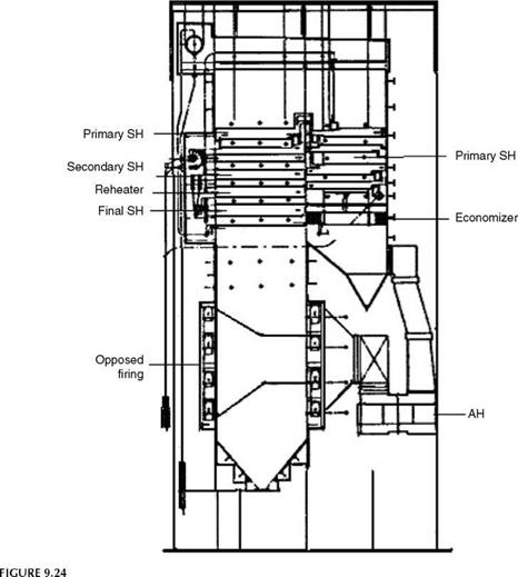
The disadvantages of the two-pass design are the advantages of the tower design and vice versa. The two designs are compared in Table 9.5. A modified tower-type boiler is a two-pass boiler with drainable surfaces as shown in Figure 9.24. It is a design that combines the advantages of two-pass and tower-type designs.
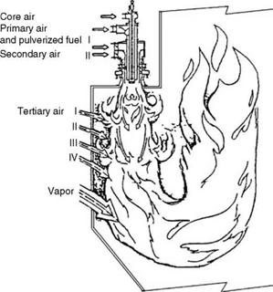
Down shot-fired boilers are employed where the VM of coal is low, <20% or lower on a dry ash-free (daf) basis. The ignition temperature of such coals is high and the burning is slow, requiring refractory lining of furnace and large furnace volume, respectively, to complete the combustion. The firing in burners is nonturbulent, with the burners facing downward such that the flames are long and there is a lot of time to burn the coal as the flames travel downward and take a u-turn. This type of boiler is described in detail in Section 13.4.8. Down-shot firing can be U-type with a single set of burners on one side of the furnace as in Figure 9.25 or W-type with burners on either side as in Figure 9.26, depending on the size of the boiler.
Bank tube suspension
|
FIGURE 9.23 Tube arrangement in a tower-type boiler. |
|
& |
![]() I
I
Ј
TABLE 9.5
Two-Pass versus Tower-Type Boilers
|
|
|
|
Gas turns on convection banks Second-pass erosion
Superheater type
Superheaters and reheaters support Support elements
Start-up time Space
Erection ease Main columns
Yes and hence erosion prone
Yes on mostly ECON top tubes
Vertical and horizontal nondrainable
From roof
Outside gas path
Slower due to water in superheaters More floor space (H X W) Short but all four sides not available Six or more
No and hence no erosion No second pass
Horizontal only drainable From walls Inside gas path
Faster as SH is dry
More height (1.25 H X 0.8 W) Tall, but full access
Four
Erosion shields required on ECON top tubes in two-pass Superior dynamics in tower-type boilers Roof support is simple
Care needed for gas-swept supports in tower
Features of Supercritical Boilers
• Differences with drum-type boilers. SC boilers are constructed differently from the conventional boilers primarily in two areas—furnace and drums. The boiler operation and control also vary. The water quality requirements are more stringent and there is no blowdown.
• No drums. As there is no circulation in SC boiler and all the water turns into steam in the furnace, no steam drum is needed. However, small separating vessels are
|
Modified tower-type boiler with two passes and horizontal drainable superheater and reheater. |
Required to separate the water fraction and recirculate the water when the unit operates at different loads and pressures.
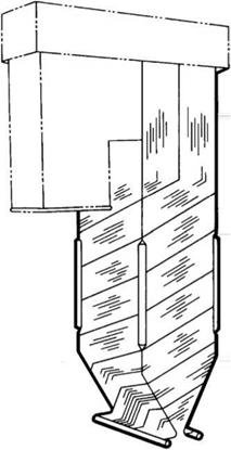
• Flow of water in furnace tubes. In the furnace, in absence of any circulation, water cannot be allowed to flow through all the tubes as the water velocity will be too low to prevent the departure from nucleate boiling (DNB). The tubes in the furnace, therefore, are grouped into circuits so that water flows through them at a good mass velocity ranging from 2200 to 2400 kg/m2 s (1.6-1.76 X 10⁶ lb/ft2 h). The circuits are arranged vertically with external pipes bringing heated water to the next circuit as in universal pressure (UP) boilers. Alternatively, the tubes can be arranged in upwardly sloping spirally wound circuits at an angle of 10-30° in the lower furnace where high heat flux prevails. They are vertical in the upper furnace where lower steam mass flow can be employed due to lower heat flux. This arrangement is shown in Figure 9.28.
|
|
FIGURE 9.25
U-type down-shot firing.
2. 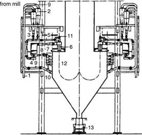 Cyclone separator
3. Rotary feeder
4. Primary air
5. Pulverized fuel boiler pipe
6. Down shot burner
7. Secondary air
8. Tertiary air
9. Vapors
10. Vapor burner
11. Oil burner
12. Furnace
13. Submerged chain conveyor
FIGURE 9.26
W-type down-shot firing.
• Vertical-tube furnace construction. Vertical tubes make construction simpler. The modern vertical furnace employs ribbed or rifled tubes in place of the spiral. The high heat flux is effectively countered by high heat transfer rates pervading in the rifled tubes despite lower mass flows.
The early SC boilers built in the United States in 1950s and 1960s were UP-types with vertical plain tubes and mainly with constant pressure base load operation
|
|
FIGURE 9.27
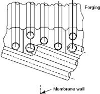
 Spiral furnace tubes for supercritical boilers.
FIGURE 9.28
Transition from spiral to vertical tube.
And at times with only load cycling. As the SC boilers achieved the highest efficiency, they were used for base loading and, naturally, the cycling duty was low. Serious problems of tube overheating required reduction of steam temperatures from 566 to 538°C.
The vertical tubes allowed nearly the same construction features of drum-type boilers. For the service intended they performed well.
The vertical tube designs continued into the 1990s even as the boiler arrangements changed. Two-pass and tower-type boilers have been built to as large as 1300 MW capacity with vertical tubes, mostly operating at 250-265 bar (—3600 to 3800 psig). The temperatures have been maintained at 538/538°C (1000/1000°F), having decreased from the earlier levels of 566°C (1050°F) during 1970s and 1980s. With metallurgical improvement, higher temperatures are used again and UP designs are abandoned in favor of multifluted ribbed tube construction.
• Spiral tube construction. Spiral wall furnaces have been in operation in Europe and Japan for many years for sliding pressure operation along with daily start/stop service. Most operate at —240 bar (3500 psig) with SOT of —566°C (1050°F) level. Steadily higher pressures and temperatures have been employed.
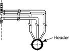
The spiral arrangement of tubes shown in Figure 9.27 is generally more expensive and complicated. The tubes are selected usually between 31.8 and 42 mm OD and spaced to suit the fin material temperature limits and usually with a gap of 19 mm as in PF boilers. There is a large pressure drop of —11 bar in the tubes, adding to the burden of the feed pump. The sloping tube panels are more difficult to build and support. The load of the lower spiral furnace must be transferred by means of complicated sliding straps to the upper furnace tubes. The number of welds is greater. The transition to vertical tubes from spiral arrangement is done at a height where the heat flux is low with the help of transition pieces with suitable headers. This adds cost, welds, and fabrication time. This transition is usually achieved by the use of mixing header to achieve uniform steam enthalpy at the inlet to upper furnace. This arrangement is shown in Figure 9.28.
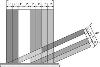
For the same circuit, the number of spiral tubes required is lower as shown in Figure 9.29; at 30° inclination, the number reduces to half. Unlike the vertical tubes,
|
8P
FIGURE 9.29 Reduction in number of tubes in spiral wall. |
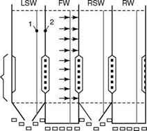
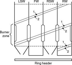
As the spiral tubes wind around the furnace, all the tubes are equally exposed to the varying heat flux incident on the walls. This minimizes the differences in tube-to-tube heat absorption, making the entire wall expand and contract like a single tube (Figure 9.30).
Figure 9.30 shows the four walls of the furnace with the adjacent tubes identified as 1 and 2. Both tubes will have nearly the same heat pickup in the spiral wall, while the heat pickup is different in the vertical wall.
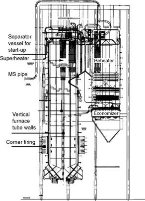
• Vertical or spiral for future? Over 600 SC boilers are in operation worldwide. There is a discernable trend toward higher steam pressures and temperatures and vertical and spiral tubing. Vertical tubing with ribbed tubes and low mass flows of <1000 kg/m2 s (—750,000 lb/ft2 h) appears to be the future direction because of cost advantage and simplicity. The cycling aspects of spiral tubing need to be built into this arrangement. Figure 9.31 shows a subcritical PF boiler of vertical-ribbed tube construction.
• In OT boilers, feed pump speed and turbine throttle are used to control steam flow and steam pressure. SH steam temperature is controlled by fuel firing rate, while RH steam temperature is controlled by gas recirculation (GR), excess air, and attemperation in combination. Gas tempering is used for temperature control entering the SH.
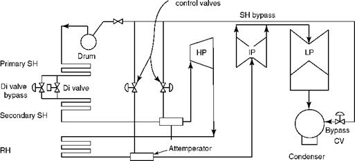
• For maintaining a safe minimum flow through the furnace tubes at all times, a steam bypass arrangement, which dumps the steam to the condenser at low loads, is an integral part of the boiler and turbine system (Figure 9.32).
• Aside from the furnace construction and circulation-related aspects, the remaining parts of the SC boiler are similar to conventional boilers in sizing.
• Two-pass, tower, and modified tower types are the common configurations for coal-fired boilers.
|
Heat Flux |
|
Burner Zone |
![]()
|
Ring header |
![]()
|
Orifices |
![]() Heat
Heat
Flux
FIGURE 9.30
Spiral and vertical tube arrangements in supercritical boiler furnaces.
|
FIGURE 9.31 A 300-MW two-pass subcritical boiler with vertical-ribbed tubes with low-mass flow. (From Doosan Babcock Energy Ltd., U. K. With permission.) |
Attemperator
|
FIGURE 9.32 Flow bypass to condenser for drum-type boilers. |
|
FIGURE 9.33 Typical modern 800 MW standard supercritical boiler. |
Drum-Type or Supercritical Boiler?
The answer depends on local conditions. The following paragraphs examine the pros and cons:
• Both drum and SC boilers are built to very large capacities. In terms of size and boiler efficiency they are nearly the same. The SC boilers have separator vessels in place of heavy drums, but the tubing in the furnace is an alloy material and furnace construction is more expensive. The draft plant in the SC boiler is a bit smaller, but the feed pumps are required to operate at higher pressure. The valves, mountings, and fittings are heavier and more expensive in SC boilers. On the whole, the SC boiler is more expensive than the drum type, with the gap reducing as the capacities increase and more boilers are built. One has also to factor life cycle costs to realize the full impact.
• A power plant operating at SC conditions is more efficient compared with the plant at subcritical pressures due to better cycle efficiency and variable pressure operation. The plant is also more flexible in operation. But the difference in efficiency is rather small if the SC station is base loaded. The boiler, piping, turbine, and feed station are all more expensive due to higher pressure and metallurgy. The incremental costs are not offset by base-loaded pit-head stations with low fuel costs.
• The comfort level of the plant owners also comes into play as an SC system demands greater O&M skills from the staff. Water quality is also more demanding for an SC boiler.
• It is generally accepted that SC plants are viable beyond —300 MW, which means that the grid should also be large enough.
Standard Plant Configurations for Supercritical Boilers
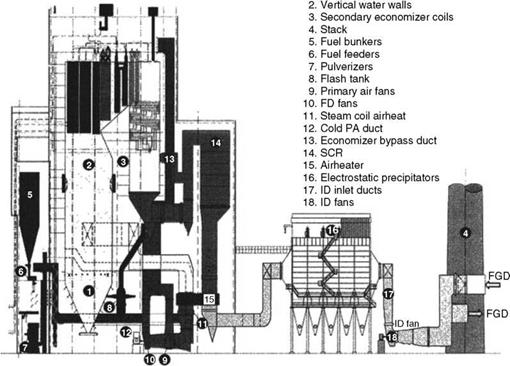
To optimize the costs of SC plants, large power plant makers from Japan, South Korea, and recently China advocate standard plants in the sizes of 600, 800, and 1000 MW capacities. One such plant for 800 MW is shown in Figure 9.33.
Further Readings
Benson boilers for maximum cost effectiveness in power plants. Siemens Power Generation Group.
Black and Veatch, 1996, Power Plant Engineering, Chapman & Hall, New York.
Brundle, B. and Babcock, M., 2002, World firsts for Yaomeng with vertical-tube low-mass-flow, Benson Unit, Modern Power Systems, July.
Cosmann, R., Schwendig, F., and William, J., Steam Generators of the Single Pass Type, Steinmueller, Germany.
Franke, J. and Kral, R., 2003, Supercritical boiler technology for future market conditions, Parsons Conference.
Franke, J. et al., Steam generators for the next generation power plants—aspects of design and performance, Siemens Power Generation Group.
Goidich, S. J. and Bose, A. C., 2005, Design Aspects of Ultra Supercritical CFB Boilers, International Pittsburgh Coal Conference, Pittsburgh, PA, Sept 12-15.
Koreans set a standard for SC systems, Modern Power Systems, May 2002.
Luby, P., 2003, Supercritical systems, Modern Power Systems, August.
Lundqvist, L. et al., 2003, A Major Step Forward—The Supercritical CFB Boiler, Foster Wheeler Energia Corporation, Powergen International.
Mcdonald, D. K., 2001, Vertical tube, variable pressure furnace for supercritical steam boilers, B&W Company and S. S.Kim, US DOE, Powergen International.
Power from wood, a special report, Power, Feb 1980.
Richardson, M. et al., Supercritical technology matures, Babcock Hitachi.
Schwendig, F., 1996, Comparison between natural circulation and once-through steam generators, L&C Steinmueller, Germany, January.
Smith, J. W., 1998, Supercritical (once-through) boiler technology, B&W USA, May.
Vishwanathan, R., Armor, A. F., and Booras, G., 2004, A critical look at SC power plants. EPRI, Power, April.
Vitalis, B. P., 2006, Constant and sliding pressure options for new supercritical plants, Riley Power Inc, Power, Jan-Feb.


 1 сентября, 2013
  admin
admin 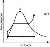
 Опубликовано в рубрике