Burner. A burner brings together the fuels and air in right proportions and admits them into the furnace chamber to accomplish combustion in an efficient and safe manner. It mixes and burns the fuel but does not control it. The proportion and regulation are performed externally for fuel and air by control valves and dampers, respectively.
Burners consist of four subassemblies:
1. Atomizer for oil and spuds/pipes for gas—for proper fuel admission
2. Air register for dividing and supplying the air with a proper swirl to provide adequate turbulence
3. Igniter for lighting the fuel
4. Flame monitor for checking the health of the flame
The shape and size of the furnace helps to develop the flame properly and achieve the completeness of combustion. Burner sizes have grown dramatically. Approximately 2 tph of oil firing per burner was considered maximum in 1960, which grew to —8 tph by the 1970s. There has been no significant increase in burner capacities, but the efforts focused on environmental compliance.
Burner size is always designated by the diameter of its throat—the slightly narrowed channel in the air register through which all air is directed toward the combustion area of the burner. As combustion air accelerates in the throat, there is a corresponding drop in pressure. The differential pressure so created can be used to measure the airflow.
In parallel flow air registers, the swirler is normally half the size of the throat. In the swirler, —35% is blanked and 65% is free for air. Throat sizes vary from 250 to 900 mm (10 to 36 in.) and more for land boilers. Single-burner capacities exceed 7 tph of oil firing or 90 MW/h (—75 m kcal/h or —300 MBtu/h).
• Turndown is the range of flows in which combustion is stable. It is the ratio of stable maximum to minimum flow. The term covers the boiler, burner, and atomizer.
• Atomizer turndown refers to oil, whereas burner turndown refers to air and oil regulated by the upstream regulating valve and damper, respectively.
• Any turndown inevitably results in pressure loss. Higher turndown means higher pressure losses of both fuel and air.
• Turndown ratios of 1:4 for the whole oil or gas burner and 1:10 for oil atomizer are normal and adequate for most boiler duties with 100-150 mm w. g. (4-6 in.) of air pressure loss. Turndown ratios of 1:6 for oil and 1:10 for gas are also possible at the expense of more air and fuel pressure losses. Gas pressure of 1.75 atg (—25 psig) in the burner manifold at full load is needed for 1:10 gas turndown so that at 10% load, the gas pressure is 0.0175 atg or 175 mm w. g.
• Boiler turndown ratio of 1:4 is normal for oil — and gas-fired boilers. For more turndown, higher air loss has to be provided with a bigger FD fan having higher head. Alternatively, the number of burners in operation can be reduced with manual intervention.
Hot air and combustion efficiency.
• Completeness of combustion with the least excess air is the goal of both a good burner design and operating practice.
• For complete and swift combustion, hot air is normally used at temperatures of 200-300°C (—400 to 600°F).
Completeness of combustion is defined as the full oxidation of all the combustible elements in the fuel. In most cases, the unburnt carbon loss in oil and gas firing is considered negligible, thereby meaning that the combustion or carbon burn-up efficiency is nearly 100%. For heavy FOs, unburnt loss can be 0.1%. This loss is measured by the CO levels in flue gas, which, at <200 ppm at 3% O2 level, is satisfactory.
From NOX generation, cold air is preferred, as discussed in Section 10.2.8. This defeats maximum efficiency and a compromise between CO and NOx has to be made.
Opacity of stack is the visible indication of completeness of combustion.
• Dark plume represents incomplete combustion and can be corrected by optimizing the combustion parameters.
• White plume is due to fumes of sulfuric acid, and excess air should be controlled.
• Light brown haze is the desired opacity.
|
|
|
Front firing |
|
Corner firing |
|
Roof-mounted firing |
|
|
|
Floor-mounted firing |
|
Opposed firing |
FIGURE 10.1
Various burner positions.
Air registers are the fabricated portions of the burners fitted to the windbox through which air is admitted. They hold the fuel-firing parts in position, namely, the oil atomizers and the gas rings and spuds. The shape of the air register gives the burner its name.
There are two types:
1. Tangential, mounted in furnace corners
2. Circular, mounted on furnace walls
Depending on the entry of air, the circular burners are classified as
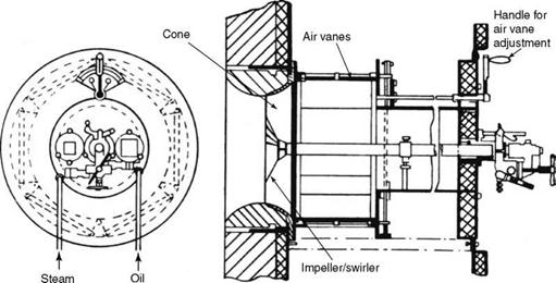
1. Tangential flow or register type producing short and bushy flames (Figure 10.7)
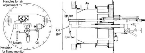
2. Parallel or axial flow type producing long flames (Figure 10.8)
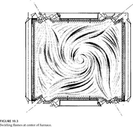
Burner types and location. Burner arrangements are extremely flexible. They can be wall mounted, corner mounted, roof mounted, or even floor mounted. Figure 10.1 depicts turbulent or wall burners or circular burners, except for the corner-fired burners, which are tangential. There is an intense mixing of air and fuel, resulting in short and hot flames in circular burners. In tangential burners, air and fuel travel in parallel paths and toward an imaginary circle in the center of the furnace where intense mixing and combustion occur. The whole furnace acts as a burner.
Circular versus Tangential Burners for Oil or Gas
Circular burners are more common because
• The tangential burners need nearly square furnaces
• A set of four burners have to act together
|
|
|
Windbox |
|
Burner assembly |
|
FIGURE 10.2 Tangential oil and gas burner assembly. |
|
Air control Oil gun Oil supply Primary air Secondary air Air control |
|
— Oil supply |
This arrangement naturally rules out smaller quantities of oil and gas firing. The package-type boilers with long furnaces are also ruled out. Tangential burners are used for large integral furnace boilers. Radiant boilers are particularly used for waste gases whose volumes are large. In tangential oil and gas burners (Figure 10.2), the flows of oil, gas, and air are parallel to each other, meeting tangentially on an imaginary circle in the middle of the furnace. Thereafter, the furnace shape provides the necessary swirl. This is shown in Figure 10.3.
Arrangements with Circular Burners
Circular burners on the front wall are the most popular arrangement. Opposed firing is done when the boiler size exceeds a certain size. Floor and roof mounting saves the plan area of the boiler and makes use of the long furnace shaft for full development of the flame when it suits the layout. In floor mounting, access to the burner is very good, and the piping is short but the boiler gets raised by —3 m. The reverse takes place for roof mounting. The boiler layout determines burner location.
Excess Air for Oil and Gas Firing
This depends on the following factors:
• Stoichiometric or 0% excess air does not help attain complete combustion, as some fuel escapes. Air should be at a minimum to contain stack loss and attain best efficiency.
|
|
|
Nominal burner capacity (%) FIGURE 10.4 Excess air at part loads and air leakage. |
• Between 5 and 15% excess air is normal, depending on the burner and the furnace geometry with all burners in operation.
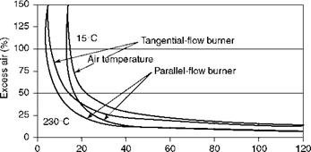
• At part-load operation, the air velocity and turbulence get reduced, affecting the combustion efficiency. To compensate, the excess air is increased. With no reduction in the number of burners, the increase of excess air is steep at low loads, as shown in Figure 10.4. The excess air increases with parallel-flow registers, and hot air is lower.
|
Burners idle (%) |
FIGURE 10.5
Air leakage through idle burners.
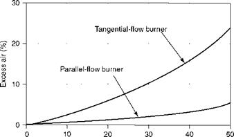
• At some point, it is better to cut out a burner than increasing the excess air. Some air has to be passed through the idle burner to keep it cool. This air requirement is shown in Figure 10.5.
• Air exceeding the minimum requirement from the point of combustion efficiency, is an easy way at part loads to restore the falling superheater (SH) temperature and thus increase the steam temperature control (STC) range.
• Low excess air reduces the back-end temperature, which can then slide into corrosion range below a certain minimum temperature level. In such cases, excess air may be required.
Improvements in atomization of FO and distribution of fuel gas and greater turbulence given to air streams by better geometry of the air register allow better contact between air and fuel. As a result, the excess air in burners has been progressively reduced over the years.
With tangential airflow in register burners, the excess air is between 10 and 15%. The combustion is very vigorous, and the flame is bushy and close to the burner with a short flame length. The burners in smaller package boilers with restricted furnace dimensions and light-up guns in PF burners are examples of register burners.
In parallel-flow burners containing excess air levels of 5-10%, air flow moves parallel to fuel flow. The swirler at the throat is shaped to allow rotation of the primary air (PA) flowing through it to help develop a small negative pressure zone to anchor the flame to the front of the swirler. A twist of the PA is better for combustion than tangential flow of secondary air (SA).
Venturi burners. A low excess air level of 5% with oil and —3% with gas can be attained. For this reason, the parallel-flow burner has to be slightly modified to a Venturi shape for better mixing and better measurement. The flame is long, and the burning is stretched.
Parallel-flow registers are the industry norm today. Low-NOx burners are intended to achieve excess air of 2.5%.
Gaseous fuels require lower excess air than liquid fuels, as they can more easily disperse and mix with air than any liquid fuel with the finest of atomization.
Excess air levels are 10-15% for normal and 3-5% for low excess air burners. Low excess air burners are superior in construction and operation. They have not superseded the normal excess air burners yet, and the industry continues to favor both.
The advantages of low excess-air burners are as follows:
• Low excess air improves the boiler efficiency.
• They reduce NOx.
The disadvantages are as follows:
• More furnace volume because the flames are long.
• More SH surface because the gas flow is less.
• In multiple-burner boilers, accurate airflow measurement should be provided or burners will operate at substoichiometric conditions and others will require extra air.
• O&M costs increase and the system is less tolerant to operational errors.
In industrial boilers, in general, and in packaged boilers, in particular, with smaller furnaces and premiums on space, burners with normal excess air are favored.
Combustion of Oil and Gas in Circular Burners
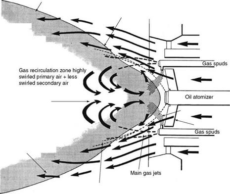
Figure 10.6 depicts the development of a flame cone in a circular burner, its stabilization on the impeller/swirler, and the recirculation of hot gases to help ignition. It also shows the PA penetrating the oil mist and SA giving the flame shape. As in any combustion reaction, there are several simultaneous actions at work:
• Air is split into PA and SA and, at times, also into tertiary air (TA) for a better mixing of fuel and air and also for greater control.
• Primary air travels parallel to the fuel and penetrates the oil and gas streams, helping ignition and partial combustion, whereas the SA travels tangentially or parallel to the fuel to complete the combustion and contain or control the flame shape.
• Primary air passes through the swirler or impeller or diffuser, which provides a twist to the air as it tries to penetrate the cone of oil mist emanating from the atomizer. This promotes a vigorous swirl to the PA and the oil mixture.
• The swirler provides a low-pressure zone in its front, where the hot combustion gases tend to recirculate and provide ignition. This is also aided by the radiation from hot furnace gases.
• The ignited oil flame settles at the swirler front. The fuel gas, if present, is also injected into the same low-pressure region at an angle to match the angle of the swirler, and the gas flame also settles there.
• Secondary air traveling tangential or parallel to the flame helps to complete the combustion and shape the flame. With a greater swirl to the SA, there is a higher air speed that accelerates combustion and makes the flame wide and short. Thus, the adjustment of air vanes regulates the flame shape.
|
|
|
|
|
|
|
|
|
|
|
|
|
|
|
|
|
|
|
|
|
• In parallel-flow registers, there is no flame-shape control. The sliding of the air door is only for on-off duty. The flame is always long and tubular.
• The atomizer is always concentrically placed to the swirler with oil holes —20 mm away, with no impingement of spray on the swirler or the burner quarl (refractory setting).
• The refractory quarl of the burner has a very important role to play. The refractory holds the heat and radiates onto the flame for better combustion, hence aiding ignition. At the same time, it protects the furnace tubes from erosion damage due to the swirling burner gases (Figures 10.7 and 10.8 and Table 10.1).
Atomizers are used for liquid fuels and two types are available. Atomization is the process of breaking down the oil film to a fine mist to enable completion of combustion in the shortest time within the confines of the furnace. It can be achieved mechanically or with the aid of steam or air.
|
FIGURE 10.7 Register-type circular burner. |
|
FIGURE 10.8 Parallel-flow type circular burner. |
|
Parameter |
Register Burner |
Parallel-Flow Burner |
|
Airflow with respect to atomizer |
Tangential |
Parallel |
|
Flame shape |
Short and bushy |
Long and narrow |
|
Excess air |
High at 10-15% |
Low at 5-10% |
|
NO, |
Higher |
Lower |
|
Furnace volume required |
Less |
More |
|
Application |
Small package boilers or short flame needed |
Large package boilers or field-erected boilers |
|
TABLE 10.1 |
|
Register versus Parallel-Flow Burners |
![]()
|
0 10 20 30 40 50 60 70 80 90 100 110 120 130 140 150 Temperature (°C) |
|
S5U tlNla 37.5- |
|
1.25 1.30 1.35 1.40 1.50 1.60 1.70 1.80 2.0 2.5 3.0 |
|
40- |
|
45 50- |
|
70 -80- |
|
Ј (0 O |
|
Pr. atom 100 H |
|
Rotary cup ———- 200- St. atom. 250 30040050075010001500- ^——— 2000 — Easy Pumping — 40006000- Pumpable _ ——— 10000- |
|
5.0 6.0 8.0 10.0 15 20 30 40 50 75 100 150 200 |
|
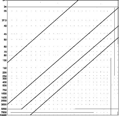
For both types of atomization, oil has to be made sufficiently thin by heating to an atomizing viscosity. • For steam atomizers, the viscosity of oil is required to be between 200 and 250 SSU, although for a wide turndown, the desired range lies between 100 and 150 SSU. • For mechanical atomizers, it is required to be a bit thinner at 80-120 SSU. This means the oil should be heated to approximately • 60-70°C for light oils • 95-105°C for heavy oils Care is needed with the heating of heavy oils. At higher temperatures, vapor formation can take place, leading to the vapor locking of oil lines and atomizer. This vapor locking is dangerous because it would result in a flame blowout followed by reignition, which can lead to furnace explosion. Figure 10.9 shows the viscosity variation with temperature for various FOs, which can serve as a good guide for FO transport, storage, and combustion. The viscosity graphs make it easy to predict the properties of FOs. Also refer to Figure 3.9 for additional information on handling of FO. Standard temperature (°F) — Minimum flash point ___ 40 60 80 100 120 140150160 180 200 220 240 260 280 300 CSt -2.75 -3.0 -3.5 -4.0 -4.5 -5.0 -6.0 -7.0 -8.0 -10.0 -12.5 -15 -20 -25 -30 -40 -50 -75 -100 -150 -200 -300 -400 -500 -750 -1000 -1500 -2000 |
|
FIGURE 10.9 Viscosity versus temperature for fuel oils. |

|
Windbox
FIGURE 10.10 Rotary-cup burner with forced-draft fan arrangement. |
Centrifugal or Rotary-Cup Atomizers
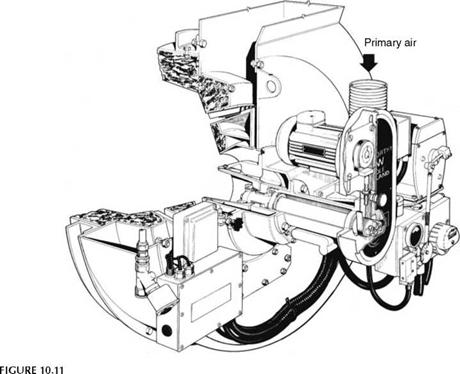
Rotary cup is a popular method of mechanical atomization. A cast aluminum cup rotates at a high speed, typically at 8,000-10,000 rpm, and the heated oil introduced at the center spreads out by the centrifugal force to form a fine mist.
• Rotary cups are simple, rugged, and reliable.
• Turndown is limited and the atomized particles are coarser.
• Maintenance increases because the moving parts are exposed to heat.
Burners that handle up to 4 tph of oil can be built on this principle. Gas firing and dual firing can also be done in such burners. Gas is introduced in the annular space.
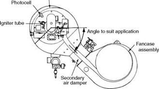
Rotary-cup burners are used in furnaces and marine boilers where short flames are needed, and the firing equipment has to be compact. They are not popular for land boiler application (Figures 10.10 and 10.11).
Pressure Atomization
The most popular type of mechanical atomization involves pressure. Oil is pressurized to —40 to 70 ata depending on the desired turndown. The two types of pressure atomization are variable and fixed pressures.
1. Variable-pressure atomization. Only the required amount of oil, as dictated by the load demand, is controlled and admitted into the boiler. The oil flow control valve is upstream of the burners. Burners receive oil at variable and lower pressures as per load. Owing to the lower pressure, the atomization is not as good as that in the fixed-pressure system, but there is no return of hot excess oil to the oil tank, which is wasteful and can lead to coking of oil.
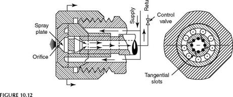
2. Fixed-pressure return-flow atomization. All the oil is pumped to the atomizer tips and the excess oil is regulated and returned to the oil tank. The tips have tangential slots to produce a swirl. Full pressure is always available at the burner tip, which gives a better quality of spray. This is a more common arrangement for a more stable flame and better turndown. Even 10:1 turndown is possible for the atomizer with 70 ata oil pressure. With 200-300 mm wg windbox pressure, the turndown range is about 1:3 for the burner in total.
|
Rotary-cup burner. |
Pressure atomization has the advantage of requiring no other medium such as steam or air and hence is very simple and convenient. But it has many limitations.
• Power consumption is greater because the atomizing pressure required is higher.
• Turndown is lower at 1:3 or 1:4 at best.
• Wear of tips is continuous and the resulting atomization is poorer, leading to a loss in combustion efficiency over time.
Pressure atomization is useful as a start-up system when the plant has no steam. The regular duty can be taken over by the steam atomizer after the start-up. It is also beneficial in multifuel firing in which oil is not the prime fuel (Figure 10.12).
Basics. Steam is used to shear the film of oil and produce the fine mist.
• Oil pressure required is a maximum of 20 bar (—300 psig) to get a wide atomizer turndown of 20:1.
• Corresponding steam atomizing pressure is —10 bar (—150 psig), depending on the design.
• Most systems operate at 7 or 10 bar oil pressures (100 and 150 psig). A limited turndown of 6:1 on the atomizer can be realized with an oil pressure of 7 bar (100 psig), which is the minimum limit.
|
Tip of return-flow atomizer. |
• Steam consumption is —10% of oil consumption, which works out as 1.5% steam generation.
• Usually, the steam pressure is held constant and the oil pressure is varied with load.
Atomizing steam consumption. Steam consumption for atomization remains almost constant at all conditions. It would, therefore, appear to go up at low loads as a percentage of steam output. To minimize consumption, the pressure is also varied with oil pressure, keeping a differential of —1.5 kg/cm2 with the help of a constant differential-pressure valve. There are also schemes in which the atomizing pressure is held constant at higher loads and varied at low loads to economize on the steam. Atomization of steam is a loss on two counts.
1. Nearly 2% of the steam generated is not available for final use and is wasted.
2. This steam adds to the stack loss reducing the boiler efficiency.
It, therefore, pays to adopt a system that consumes minimum atomizing steam.
Care of atomizer tips. As the steam consumption increases with dirty and worn-out tips, it is essential to maintain the tips by frequent cleaning and replacement. In large oil-fired power stations, it is economical to have separate package boilers to supply atomizing steam.
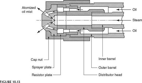
The atomizer tips are precision components machined from heat-resistant steel bar and nitrided to high hardness levels so that the holes retain their shape and dimensions for a long time (Figure 10.13).
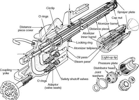
Atomizer construction. Both steam — and pressure-jet atomizers are tubular in construction, varying in diameter only from —50 to 80 mm, as the liquid fuels are of high calorific value (CV) and compact. Suitable removable tips are screwed at the furnace end, whereas the atomizer bodies or heads with handles are toward the operating platform. The central pipe of the burner supports the atomizer. Spring-loaded connections in the atomizer body permit safe connection and disconnection with the oil supply lines. This is shown in Figure 10.14.
A single pipe is sufficient for a pressure atomizer and a pipe-in-pipe arrangement is suitable for steam or air or return-flow atomizers. Steam always flows through the central pipe of the atomizer and oil in the annulus.
|
Tip of steam jet atomizer. |
|
|
|
Locking bolt and plate |
|
Handle |
|
Atomizer body |
|
FIGURE 10.14 Assembly and parts of typical steam jet atomizer. |
Atomization process. As the steam expands into the outlet nozzle, the pressure drops at the vena contracta to vacuum levels. There, the oil gets sucked through the holes to form an emulsion and jets out as a mist. Shearing of oil film by steam produces very fine droplets. The thin steam shears the thick oil film. The difference in viscosities causes the shearing of oil film.
|
Pressure versus Steam or Air Atomization
|
Because the steam attains vacuum levels to pull the oil in the nozzles, it is not necessary that steam pressure should be lower than the oil pressure. In constant-pressure atomizing systems, the steam pressure is higher than the oil pressure at lower loads.
Turndown. Steam-jet atomizers individually can give a wide turndown of 20:1. Figure 10.14 depicts the tip assembly.
Interchangability of atomizer tips. Usually the steam — and pressure-jet tips of return flow design can be interchanged. In PF burners, the light-up duty is handled by the pressure-jet atomizer and load carrying on the steam jet. The same assembly can be used with interchangeable tips.
Air-jet atomizers. The performance of air-jet atomizers is comparable with that of the steam jets. But the cost of an air compressor to provide high-pressure air in large quantities is more expensive. However, in process plants for black start-up operation, it is normal to adopt air-jet atomizers (Table 10.2).
Air registers are for distributing and directing air for proper combustion. For both gas and oil burners, the same types of air registers are used. However, the difference is in the way the fuel is taken to the combustion zone and mixed with air. For liquid fuels, it is done with atomizers, whereas for gaseous fuels, some type of piping arrangement is required. As the fuel gases change widely in pressure, heating value, and temperature, the gas volume correspondingly varies, making the burner sizes and shapes alter significantly. Unlike the oil burners, the gas burners are available with a wide variety of constructions.
As the gas pressures and CV are lowered, the volumes increase, calling for larger gas pipes, which in turn, require different burner designs as listed in Table 10.3.
Circular Multispud-Type Natural Gas Burners
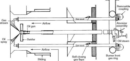
Natural gas firing is easy in circular burners with multiple spuds as shown in Figure 10.15. This design is suitable for any high-CV gas at good pressure, as given in Table 10.3.
|
TABLE 10.3 Burners for Various Gases at Various Pressures
|
|
Air register FIGURE 10.15 Circular multispud burners with parallel-flow register for combined oil and gas firing. |
• The gas ring, usually located outside the burner (or attached to the front plate and on the rear side to give a clean facade), has several spuds (pipes) branching off toward the swirler where the nozzles direct gas into the PA zone.
• A minimum gas pressure of —175 mm wg or mbar is required in the gas ring and accordingly, for 1.75 barg pressure, a turndown of 1:10 will be possible.
• Each spud has three to four nozzles of —10 mm diameter, depending on the gas pressure and the type of gas. By adjusting the orientation of the jets on the spuds, the flame can be made luminous or nonluminous. This is a great advantage in multifuel firing because the luminosity can be matched.
• Each spud has a collar to stabilize the flame at low loads.
• Each spud is joined to the gas ring by elbows in such a manner that it is possible to disconnect and take out the spuds for inspection. A flap door on the spud sleeve prevents the leakage of hot gases to the outside.
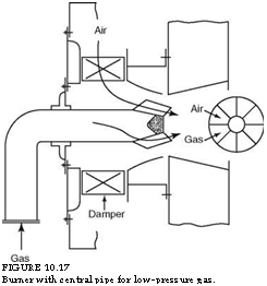
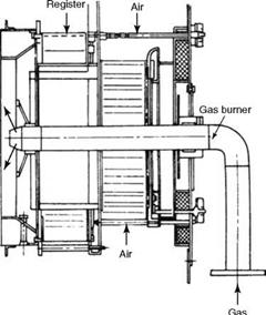
• When the gas quantity is small, a central gas pipe with suitable holes may be adequate in place of multispuds.
The design and selection of the burners depend on the
• Calorific value of the gas
• Delivery pressure at the burner manifold
• Delivery temperature
• Multifuel firing requirement
|
FIGURE 10.17 Burner with central pipe for low-pressure gas. |
|
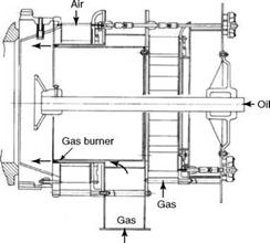
Air FIGURE 10.18 Ring-type burner for medium-pressure gases. |
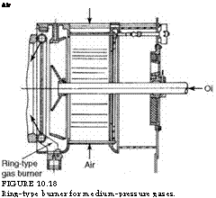 Burner designs can assume a great variety. Table 10.3 gives some of the gas-burning possibilities in a simple manner. These burners are found mostly in process industries (Figures 10.16 through 10.19).
|
FIGURE 10.16 Burner with central pipe for high-pressure gas. |
|
FIGURE 10.19 Scroll-type burner for low-CV gases. |
NOx in flue gas is the result of oxidation of otherwise inert nitrogen under the influence of high temperature. Two types of reactions promote the NOx formation:
1. NOx due to the nitrogen in fuel
2. Thermal NOx due to the nitrogen in air
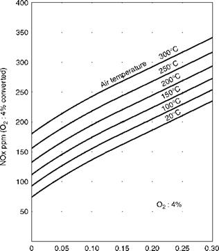
Heavier oil leads to higher nitrogen content. Light oils and kerosene contain nitrogen of —0.01% by weight it increases to 0.3% in heavy oils. Fuel gases contain nitrogen in the form of NH3, HCN, etc. Typical NOx generation with normal burners with cold and hot combustion air is depicted in Figure 10.22.
Circular burners with parallel — or axial-flow registers have already been explained. The low NOx burners are modified axial-flow burners with:
1. Reduced excess air
2. More split air streams
3. Gas recirculation (GR) at times
The working principle of low-NOx burners is illustrated in Figure 10.20, whereas Figure 10.21 depicts construction. All the above-mentioned factors work concurrently to produce low NOx in the furnace.
• Lowered excess air reduces the tendency to form NOx due to the scarcity of oxygen.
• As the air stream is split, the combustion takes place in stages, and this protracted combustion does not permit flame temperatures to reach their peak.
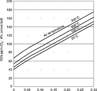
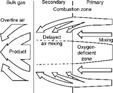 Thus, the flame is starved of both temperature and free air, suppressing the NOx- forming tendency. These measures are adequate to secure more than 50% NOx reduction. To attain as high as 70% reduction, flue gas from the furnace is recirculated and the air temperature to the burners is reduced to the minimum. The mass flow in the burner is maintained in this way for adequate turbulence but with no addition of oxygen. NOx generation with normal circular burners is depicted in Figure 10.22, whereas Figure 10.23 represents the reduction in NOx when all the three above-mentioned reduction measures are applied.
Auxiliary air Gas
Recirculation
Fuel-rich coal nozzle
Auxiliary air
FIGURE 10.20
Working principle of low NOx burner.
FIGURE 10.21
Typical low-NO, burner.
|
|
Fuel N (%)
FIGURE 10.22
NO^ generation with normal burners.
|
Fuel N (%) |
|
TABLE 10.4 Igniter Classification
|
|
Note: As per National Fire Prevention Association Regulation 85E. |
|
Pilot head Electrode assembly Spark plug assembly
FIGURE 10.24 Gas-electric igniters. (From Coen Company Inc., U. S.A. With permission.) |
The purpose of an igniter is to provide the heat energy needed to ignite the main flame in a safe manner. As per National Fire Protection Association (NFPA) of United States Regulation 85E (standards for prevention of furnace explosions in PF fired multiple — burner boiler furnaces), which deals with safety in design and operation of oil — and gas — burner equipment, the igniters are divided into four classes as given in Table 10.4.
Igniters can be stationary or retractable, the latter being preferable. With the stationary type, adequate cooling air must be supplied.
Gas-electric (GE) igniters, shown in Figure 10.24, are the most common igniters, as the electric spark has to ignite a clean fuel such as LPG, which in turn, ignites the main fuel. The spark igniter performs light duty, and it stays clean. The gas burns easily and provides a big flame for the main fuel to catch fire. The igniter includes a flame monitor to view the pilot flame. GE igniters are reliable, durable, almost free of maintenance, and extremely simple. If the NG or the LPG is available, this system is always preferred.
The capacity of the igniter should be —1% of the burner capacity. The reason is that the low-fire light-off of a burner should be done at —20% of its rating, and the pilot flame should supply —5% of that. Gas supply pressure should be >700 mm wg, and the pilot flame size —1500 mm long and 500 mm diameter.
High-energy arc (HEA) igniters shown in Figure 10.25 were developed for directly igniting the low grades of fuel oil without the need for an intermittent expensive fuel such as gas. The spark is capable of heavy duty. The advantages of this system are as follows:
• The elimination of the light-up fuel system that includes storage and handling
• A single flame-monitoring system
For the igniter to operate reliably, the only requirement is that the electrode should be free from any carbon and other deposits to ensure a strong spark for a safe light-up.
|
Exciter Flexible electric cable
Retractor Spark rod FIGURE 10.25 High-energy arc (HEA) igniter. (From Coen Company Inc., U. S.A. With permission.) |
|
FIGURE 10.26 Hot carbon rod igniter. |
The system consists of an exciter, a flexible cable, a spark rod, a tip, and a retractor. The spark rod helps to position the tip in the right spot. The tip is a shunted surface-igniter plug that releases ignition energy in five to six rapid pulses per second. Output power level can be as high as 2000 kW peak power per spark, which is enough to ignite heavy residual oil.
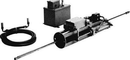
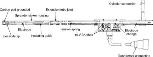
Hot carbon (HC) rod igniters, depicted in Figure 10.26, are used for direct ignition, even for heavy oils. The electrode is typically a 6-8 mm diameter and 300 mm long special carbon rod with a copper-nickel-coated outer surface that reaches a temperature of 2500°C within a few seconds of switching. The outer surface burns off, exposing 25 mm of white, hot carbon to enable the ignition of the fuel to take place. The igniter is switched off and retracted from the fuel path to a lower temperature. The electrode life is about 250 starts. This type of igniter is not suitable for gas burners with multiple gas spuds.
Table 10.5 compares the various igniters.
|
TABLE 10.5 Comparison of Igniters
|
|
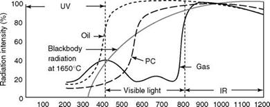
Wavelength (nm) FIGURE 10.27 Radiation intensities of various flames. (From Power Magazine. With permission.) |
Flame monitors are the "eyes" of the burner management system (BMS) and are fixed
On the burner front. There are three types, depending on the fuels fired:
1. Ultraviolet (UV)
2. Infrared (IR)
3. A combination of both
Flame-monitoring fundamentals are as follows:
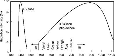
• All flames radiate energy in differing intensities from UV to IR range (as shown in Figure 10.27) captured by UV and IR scanners as shown in Figure 10.28.
• Gas flames have good emission in the UV range and are suited for UV scanners.
• Oil flames have peak emission in the IR range with sufficient emission in UV range, and both types are suitable.
• Coal flame emission is predominantly in the IR range, and the IR scanners are suitable.
• For dual fuels, a combination head is employed with both UV and IR.
• Flames also produce a flicker at the root with distinct frequency. In multiple-burner installation, the flicker is added in the scanner to distinguish the adjacent or opposite flames.
|
Wavelength (nm) FIGURE 10.28 Suitability of scanners. (From Coen Company Inc., U. S.A. With permission.) |
|
FIGURE 10.29 Components of scanning system. (From Coen Company Inc., U. S.A. With permission.) |
A flame scanning system consists of two ends—the burner end and the input end for receiving signals for BMS. In addition to the appropriate scanner, the burner-end system consists of the following components, which are shown in Figure 10.29:
1. Viewing heads at the two sides of the burner
2. Signal processors at the two sides of the burner
3. Connecting cable
4. Mounting arrangement
5. Purge-air connection
6. Shut-off valve to prevent backflow of furnace gases
Purging of the scanner is very important. The instrument needs to be kept cool, preferably at temperature <70°C.


 3 сентября, 2013
  admin
admin 


 Опубликовано в рубрике