The classical or the full-circulation CFBC process involves
• Operating at higher velocities of —4 to 7 m/s
• Using high ash recirculation for uniform temperature profile
• Controlling the combustor temperature near optimum desulfurization temperature
• Employing staged combustion to limit NOx
• Releasing high heat rates in plant areas closer to PF boilers
Circulating fluidized bed combustion is an exceptionally versatile and environmentally friendly technique for the utility market.
The classical CFBC process operates at the higher end of the fluidized bed regime, just lower than the transport phase. It includes a fluid bed expanded all the way to the roof of the combustor instead of restricting the bed to the lower part as in a BFBC boiler.
|
FIGURE 12.11 Large single-drum underfeed coal-fired bubbling fluidized bed combustion boiler of 140 tph. AH, airheater; ECON, economizer; FD, forced draft; ID, induced draft; SH, superheater. |
Naturally, the dust carryover to the outside and the recirculation within the combustor are heavy. The differentiating and unique-to-CFBC system is the cyclone that collects the dust and returns to the lower combustor for temperature control, optimized limestone use, and refiring of char. The thick ash layer running down the walls of the combustor, the high turbulence, and the dense particle phase even in the higher part of the combustor do not permit any drop in gas temperature in the freeboard. As a result, the bed, the furnace, and the cyclones are all at nearly the same temperature, approximately 850°C. Although this high temperature and heavy and internal dust recirculation in the furnace and external recirculation in cyclones are good for combustion of char, they impact the cyclones that need a lot of refractory to withstand heavy erosion due to the high-velocity gas and dust stream. As the cyclones operate at such a high temperature, the classical CFBCs are also called hot cyclone designs, developed originally by Lurgi of Germany and Ahlstrom of Finland.
Circulating Fluidized Bed Combustion Boilers of Lurgi and Ahlstrom
Developed in 1970s and commercialized in 1980s in Europe, the initial designs have vastly improved. There was a lot of refractory construction originally and the gas velocities were high, resulting in a high incidence of erosion. These issues have been addressed, and second-generation designs enjoy better reliability. Many proprietary designs vanished, as the late 1990s saw a sharp decline in coal market and disappearance of many established boilermakers.
In both the pioneering designs of Lurgi and Ahlstrom, the basic parameters were highly similar except that
1. Lurgi designs employed external fluid bed heat exchangers (FBHEs) for finishing stages of SH and reheater (RH) and thus required heat transfer from circulating ash for combustion temperature control.
2. Ahlstrom used division walls and omega tube panels in the freeboard for heat transfer and temperature control.
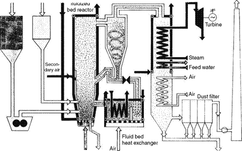
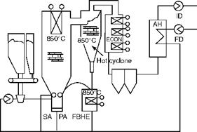
Figure 12.12 shows the hot cyclone technology developed by Lurgi. The two technologies are compared in Figure 12.13. The gas velocities, dust loading, cyclone parameters, and second-pass construction are all comparable. There are differences in the mechanical and constructional features in FBHE and platen SH as mentioned in the preceding text.
Lurgi and Ahlstrom have sold their boiler businesses. Lurgi’s boiler business is now with AE&E-Lentjes. Ahlstrom sold its boiler business to Foster Wheeler Corporation (FWC) which evolved a compact design replacing the hot cyclone. Alstom of France acquired.
• Combustion Engineering of U. S.A and Stein industries of France, the former licensees of Lurgi
• EVT of Germany, the licensees of Ahlstrom
These companies have improved hot cyclone technologies. However, the basics remain valid.
Comparison of CFBC and BFBC Boilers
• The bubbling fluidized bed combustion boiler is primarily a process device capable of generating power up to 30 MWe
• Circulating fluidized bed combustion boilers are mainly for medium and large power
• CFBC boilers offer greater flexibility as shown in Figure 12.9.
Table 12.4 brings out the differences between the two combustion systems. CFBC performance is better in nearly every way but is more expensive. But at lower than —100 to 150 tph, BFBC is much cheaper, primarily because of no cyclone, shorter height, and smaller fans. The comparison is made between multiple underfeed BFBC boiler and full — circulation CFBC boilers.
|
|
|
|
|
|
|
|
|
|
|
|
|
|
|
|
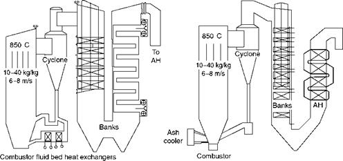
TABLE 12.4
Comparison of BFBC and CFBC
|
Parameter |
BFBC |
CFBC |
Comments for CFBC |
|
Boiler |
Short and stout |
Tall and slender |
More like PF boiler |
|
Range (—tph) |
<150 |
100-2000 |
On solid fuels such as coal |
|
Efficiency |
Good |
Better by ~4% points |
Nearly same as pulverized fuel |
|
Carbon burnup |
92-96% |
98-99% |
—5% higher due to longer residence time and contact during recirculation |
|
Thermal efficiency |
—84% |
-88% |
— 4% higher due to lower unburnt |
|
On GCV (coal) |
Losses |
||
|
Part load efficiency |
Poor |
Same up to 50% |
No bed tubes, so combustor temperature can be optimized and kept constant |
|
Bed velocity at full |
Low 1.8-3 m/s |
High 4.5-7 m/s (-15 |
Combustor plan area much smaller |
|
Load |
(—6 to 10 ft/s) |
To 23 ft/s) |
Due to lower PA and higher bed velocity |
|
Bed particle size |
0.5-1.5 mm |
0.1-0.3 mm |
Particle size lower so that it is easy to lift particles to great height |
|
Primary air: |
90:10 |
60:40 |
Staged combustion in CFBC gives |
|
Secondary air |
Lower NO^ |
||
|
Residence time |
2.5-3 s |
4-5.5 s |
Makes combustor tall and slender |
|
Heat release |
—1.5 MW/m2 |
5-7 MW/m2 |
Higher turbulence and ash |
|
(—476000 Btu/ft2 h) |
(-1.6 to 2.2 m Btu/ft2 h) |
Recirculation result in higher heat release |
|
|
Bed temperature |
Variable |
Constant |
Constant bed temperature produces |
|
Versus load |
High efficiency from 50-100% MCR |
||
|
Bed temperature |
In-bed tubes |
Ash/gas recirculation |
Smaller bed allows better |
|
Control |
Temperature control |
||
|
Bed level control |
Intermittent draining |
Intermittent draining |
|
|
Bed recirculation |
5:1 |
10-100:1 |
|
|
Turndown |
1:3 stepped |
1:3 step less |
Step-less load variation makes control easy |
|
Dynamics |
Sluggish |
High heat release and no bed coil to abstract heat make it responsive |
|
|
Start-up time |
Nearly as good as PF |
||
|
Fuel flexibility |
Good |
Better |
No bed tubes and more ash recirculation permit poorer fuels |
|
Fuel preparation |
6-8 mm (coal) |
6-8 mm (coal) |
No great care needed, higher fines can be tolerated |
|
Fines in coal (<1mm) |
<20% |
<40% |
Better tolerance for fines |
|
Alkalies in ash |
Corrosion of bed tubes |
No issues |
|
|
Tube erosion |
Bed tubes |
Furnace tubes |
Furnace tube refractory finishes erode from ash sliding |
|
Refractory erosion |
No |
Mostly overcome |
Cyclone, return leg, and furnace erosion were problems |
|
Auxiliary power |
Higher by -20% |
Higher bed velocities |
|
|
Emissions NO^ |
< 200 ppm dv |
<100 ppm dv |
Staged combustion and reducing conditions in bed due to C and CO |
|
Emissions CO |
<250 ppm dv |
<100 ppm dv |
|
|
Emissions SO^ |
< 300 ppm dv |
<100 ppm dv |
For high-sulfur coal of 3% S |
|
Limestone required |
High |
Low |
Ash recirculation results in longer contact and lower Ca/S ratio |
|
Desulfurization |
—85% |
-95% |
Very low levels achieved cannot be attained by BFBC |
|
Bed ash handling |
Many points, small quantity System messy |
Less points, FBAH System simple |
Dry and cooled ash handling. Clean and elegant |
|
Notes: The figures are rounded off after conversion. Gas velocity is the average in the bank. FB is freeboard. |
In the 1980s and early 1990s, both technologies were developed simultaneously, BFBC boilers in the United States and CFBC boilers in Europe. Both shared the fluidization principle. As the contours and the limits of the technologies grew sharper, it became clearer that they were more complementary than competing.
BFBC clearly yields
• Cheaper construction
• Lower power consumption
• Less erosion
BFBC is more suitable for smaller boilers where the environmental regulations are not very stringent. It suffers from many drawbacks.
• It is less efficient
• It can tolerate lower fines
• It has lower fuel flexibility
• It suffers from corrosion and erosion of bed tubes
• It has poorer dynamics and part load efficiencies
• It has poorer environmental compliance and produces higher NOx and SOx
Pulverized fuel boiler supremacy has been challenged seriously after its reign of more than half a century by the CFBC boiler. Table 12.5 compares the two technologies. CFBC boilers are gaining widespread use at least in the sub-100 MW sizes, due to
• Fuel flexibility
• Safety from explosions
• Environmental friendliness
• Low O&M costs
• Simpler ash handling
Pulverized fuel boilers are still the choices of utilities for firing conventional fuels, as the net output is higher by —1% over CFBC boilers due to lower fan power despite the high milling power when sulfur in fuel is not high. The lowering of deNOx and deSOx plant costs has further strengthened the case of PF. CFBC finds favor with inferior fuels (brown coals, peat, washery rejects, etc.), high-sulfur fuels, or difficult fuels (anthracite, petroleum coke, etc.). Besides the newness of CFBC, other issues cited against CFBC are its slightly higher auxiliary power and potential of erosion. In the lower range, the CFBC has practically displaced the PF where a small-sized environmentally compliant PF boiler as depicted in Figure 12.14 is expensive.
Design Features of Classical or Hot Cyclone CFBC
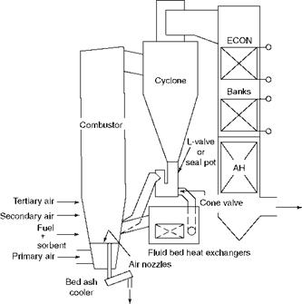
Figure 12.15 depicts a classical CFBC with hot cyclone and FBHE. The following paragraphs describe the features of the hot cyclone design.
|
Parameter |
PF |
CFBC |
Comments for CFBC |
|
Fuel preparation |
Ground to <75 |^m |
Crushed to <6-8 mm |
No fuel grinding; saving in power |
|
Fuel flexibility |
Limited |
Very wide range |
Because of inventory of hot bed material in combustor |
|
Maximum burden (A+M limit) |
—62% |
-75% |
Brown coals, peat, and washery rejects are burnt easily |
|
Abrasive fuels |
Heavy wear and |
No special wear |
Usual precautions against |
|
O&M of milling plant |
Problems |
Pressure part wear are adequate |
|
|
High-sulfur fuels |
FGD plant required |
Lime dosing with fuel |
In-furnace sulfur capture as high As 95% |
|
Oil firing |
Start-up and |
Only for start-up |
Big savings as no oil needed for |
|
Requirement |
Up to 50% |
Low-load operation |
|
|
Thermal efficiency |
—88% |
-88% |
Nearly same as PF for normal coals |
|
Auxiliary power |
Lower despite mills |
High due to fluidization |
— 2 to 4% higher due to fan power |
|
NO, ppm dv (typical) With low NO, burners |
500-1000 100-300 |
<100 |
Low due to staged combustion at <900°C |
|
SO, mg/N m3 (typical) |
—2600 without deSO, |
<100 |
|
|
Moving equipment |
Mills and feeders |
Only feeders |
|
|
O&M costs |
High |
Low |
Low O&M costs except for wear problems |
|
Soot blowers |
Many and all over |
Only in second pass |
In some designs, soot blowers can be avoided. Mostly rotary |
|
Ash handling |
Wet or dry, complicated |
Dry, simple |
Fewer points, cooler ash, and no clinker |
|
Oiler controls |
Complicated |
Relatively simple |
Limited burners and soot blowers and no mills |
|
Burner controls |
Complicated |
Very simple |
Very few burners for start-up |
|
Boiler dynamics |
Very fast |
Nearly as fast |
Big reservoir of heat in bed, provides heat as required |
|
Cold start after 48 h |
Normal time —6 h |
—2 h as bed —500°C |
Start-up times better due to heat in combustor |
|
Warm start after 8 h |
Nearly normal time |
-1 h |
|
|
Hot start |
—1 h |
—20 to 30 min |
|
|
Explosion risk |
High |
None |
Very safe boilers |
|
TABLE 12.5 |
|
Comparison of CFBC and PF Firing |
Combustion air is supplied in CFBC boilers at two levels
1. —60% at the bottom of the combustor at a high pressure to fluidize the bed
2. —40% in freeboard to complete the combustion
Fluidization velocities were 7-8 m/s (—23 to 26 ft/s) and have been reduced to —6 m/s (—20 ft/s).
|
FIGURE 12.14 Environmentally compliant pulverized fuel-fired boiler. |
|
Bed ash FIGURE 12.15 Circulating fluidized bed combustion boiler with hot cyclone, fluid bed heat exchangers, and screw coolers. AH, airheater; ECON, economizer. |
The air split results in a staged and hence low-temperature combustion. The FC burns predominantly in the lower part of the combustor and the volatiles in the upper levels. When a heavy stream of ash is added to the combustor as recirculation ash from the furnace and cyclone, the bed temperature is further depressed. There are no bed tubes for
|
Secondary air (%) |
FIGURE 12.16
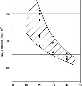
Effect of secondary air on NO,.
Maintaining the desired low temperature; control of recirculated ash handles the function. Figure 12.16 captures the effect of SA on the NOX emissions. NOX emissions effortlessly stay at <200 mg/N m3 on 6% O2 when 30% or more SA is given.
Air nozzles. In CFBC boilers, PA forms only half of total air. The bed area is also much smaller. It is usual to have fewer heavy, large-diameter nozzles typically on 200-250 mm (8-10 in.) spacing compared to numerous small-diameter nozzles on 100 mm (4 in.) spacing. The U-beam design employs BFBC nozzles.
Fuel and sorbent are always fed into the combustor from the top. Usual crushed fuel sizes are
• 10 mm or more for lignite
• 8 mm for coal and
• 6 mm for anthracite or low-volatile coal
Fines in fuel up to 40% through 1 mm and surface moisture up to 15% are acceptable. This makes CFBC an extremely versatile technology.
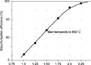
Sizing for limestone is usually 1 mm, depending on purity and reactivity. Fuel and sorbent sizing is very important for good interaction between the two. From Figure 12.17, which is for coal of 1% sulfur, very high desulfurization is achievable in CFBC boilers with relatively low lime consumption.
Fuel feeding. In most CFBC boilers, fuel and limestone are fed into the boiler along with the recirculated solids from the seal pot. This helps to flash dry the moisture and heat
|
Ca/S mole ratio |
FIGURE 12.17
Desulfurization efficiency versus Ca/S ratio.
The solids. There are usually two or four openings in the combustor to feed all the solids. The openings are restricted. Alternatively, pneumatic transport and injection through SA nozzles have been adopted.
The lower combustor, up to the level of tertiary air (TA), is always in a heavily reducing zone on account of substoichiometric air. This helps in lowering the NOx produced by the reaction of C and CO with NO2.
The lower combustor is refractory-lined to prevent tube corrosion due to the reducing environment. The refractory has to be
• Very hard to withstand bed material erosion
• Reasonably thin to reduce weight
• Optimally conductive to transmit heat to the walls
Freeboard. In addition to the high turbulence, there is an ample residence time of 4-5 s in the combustor to burn the fuel efficiently and also to desulfurize more completely. Combustor heights are typically 30-35 m (—100 to 115 ft) from the tops of air nozzles. Gas velocities are 5.5-6.0 m/s (—18 to 20 ft/s) to provide a combustion of good heat transfer to walls, lower erosion rates, and good stability at low loads during turndown.
The heavily dust-laden flue gases move at high velocity and maintain high slip between the gas and the dust. The separated dust moves along the walls in thickness of 150 mm (6 in.) or more. It is this hot layer of ash that contributes heat to the walls by conduction unlike the radiation from flames in a conventional boiler. The whole combustion chamber is nearly at the same temperature, which is desirable for combustion and desulfurization.
Tube leakage. Greater care is necessary in the manufacture of membrane panels of CFBC boilers as they experience a lot of ash flow along the tubes and consequently are prone to erosion. Any tube failure results in a lot of downtime and repair work, as the water reacts with CaO and forms huge blocks of gypsum by the time the boiler cools down. Removal of these blocks by pneumatic drills around the air nozzles is a difficult task during which a few nozzles may be damaged.
The cyclone is the heart of the CFBC system. Static and unimpressive except for its size, a cyclone is design-intensive and determines system performance.
The hot flue gases at ~850°C, along with dust, typically at 10-20 kg/N m3 (0.624-1.25 lb/ N ft3), leave the freeboard and enter the cyclones to emerge fully dedusted. The dust level is so high that it is apt to describe the mixture as gas-laden dust instead of dust-laden gas! Cyclone efficiency is —99% for particles of 100 |jm and more. The gases are accelerated to a velocity of —25 to 28 m/s (—80-90 ft/s) at the tangential entry and guided along the conical bottom. At the end of the cone, the gases disengage from dust in a reverse helix and flow upward. A high level of collection efficiency from the cyclone is very vital in realizing the performance from the boiler.
• The cyclones for CFBC boilers were developed because of the unprecedented dust levels in the flue gas. The viscosity of ash at high temperature for various materials of different particle sizes decides the cyclone performance.
• Cyclone geometries were adjusted for the best collection efficiency.
• To withstand the erosive forces of the high-velocity hot and dusty gases and to provide a fairly cool cyclone casing, a suitable thermal insulation takes the form of a dense refractory brick lining followed by layers of backup insulation. In all, a thick lining of 500-600 mm is needed.
• Very sound construction for the refractory must withstand the cutting forces and vibrations induced by the high-velocity gases. Falling refractory bricks are disastrous, as the return ash flow from cyclone to bed gets interrupted, leading to high bed temperature and boiler trip, and the cyclone wall also gets overheated.
Seal pot. The massive load of dust, as high as 40-60 times the weight of fuel in full CFBC boilers, returns to the lower combustor assisted by ash pumps (called L-valves or siphons or seal pots) to overcome the pressure difference of nearly 200 mm wg. between the combustor and the cyclone pass. An ash pump is a bubbling bed chamber that receives solids from the cyclones on one side, fluidizes them, and helps them to overflow into the combustor. As the particle size is fine and uniform, the fluidizing velocity is low at 0.3-0.6 m/s. Seal pots typically are made of CS plate with refractory lining. Because of the thick refractory lining of 500-600 mm and the massive recirculation flow of dust, the seal pot in a hot cyclone is big and maintenance-prone. Water-coded designs with much thinner lining have been developed.
The cleaned hot gases from the cyclone enter into the second pass to dissipate their heat to a series of convection surfaces such as the SH, ECON, and AH. With gases entering at —850°C, the enclosure of the second pass has to be of membrane wall construction. The design considerations for the various convection surfaces are the same as for a conventional PF boiler.
Superheater. The gas in the second pass is hot but it is devoid of dust. For steam temperatures up to 520°C (—970°F), a convection SH in the second pass is adequate. For higher SH temperature and for RH, FBHE or HS in first pass is needed for an economical design, transforming heat from the hot circulating ash.
Economizer. This is the main HS in the boiler. The design is conventional. Plain tubes are usually employed.
Airheater. Tubular AH is preferred in FBC because of the big pressure difference between air and gas. A rotary AH is economical for large-size units, especially for the lower — pressure SA. The disadvantage of RAHs is the need of expensive seals to handle the high pressure difference.
A horizontal tubular AH with gas over tubes and air inside is preferred to the vertical arrangement due to better cleanability and lower HS.
Soot Blowers. With wide spacing of tubes and in-line arrangement, SBs may be avoided. Since the deposits are loose, sonic blowers are often used.
Electrostatic Precipitators or Fabric Filters
The cooled gases at —130 to 150°C (265-300°F) are finally cleaned via a bag filter or electrostatic precipitator (ESP) before discharging into the atmosphere. The main differences compared to PF boilers are that
• The dust loading remains practically constant irrespective of the ash in fuel, as the ash is recirculated several times until the dust load attains the required concentration in terms of kilogram per cubic meter (kg/m3).
• There is substantial CaO and CaSO4 where desulfurization is done.
• The particle size is very fine in a limited band.
The dust is high in carbon for slow-burning, high-FC fuels and low-ash fuels and it is necessary to return the dust to the combustor, at least from the first two fields, to
• Improve the combustion efficiency
• Reduce the lime consumption
Ash disposal in wet form, sometimes employed in PF boilers, can be ruled out because of gypsum that will form hard rock. Dry disposal to the ash silos is the most reliable method.
For high SH and RH temperatures, external FBHE is provided in the return ash path from cyclone to combustor in the Lurgi design. The FBHE is a bubbling bed heater in which the return ash is bubbled over a bed coil comprising the finishing stages of SH and RH. The resulting low-temperature ash from the FBHE outlet controls the bed temperature and reduces
• The ash recirculation requirement
• The bed temperature variation
FBHE is usually not employed in boilers of < —250 tph capacities for reasons of economy. In FWC design, the Intrex serves a similar purpose. Intrex or FBHE is typically provided only when
• Reheating is needed. The finishing SH and RH are usually the coils in the FBHE.
• A variable HS is required to deal with multiple fuels needing different bed temperatures. The ash flow to the FBHE can be regulated, and the combustor temperatures can be kept at optimum level for each fuel.
• The combustor size in large units has to be reduced for competitive configuration. The FBHE takes part of the load and makes the combustor compact.
• A wider turndown is required. The combustor temperature is maintained over a greater load range when FBHE shares part of the load.
The heat transfer in the FBHE and fluid bed ash cooler (FBAC) coils is high, varying from 300 to 600 W/m2 °C or 250 to 500 kcal/m2 h °C (—50 to 100 Btu/ft2 h °F), which makes it a very compact HS.
Lurgi emphasized these benefits and employed the FBHE, whereas Ahlstom preferred platen surfaces in the upper combustor and the additional Intrex. Omega tubes were used in platens to withstand erosion. The argument against FBHE was the possible erosion of in-bed coils of SH/RH of FBHE, although the bed material is finer and more uniform. The construction is cumbersome with thick refractory lining of —600 mm (—2 ft) and big ash pipes and steam pipes entering and exiting. Erosion of tubes and refractory affects the availability of the total boiler. Membrane-type walls for the FBHE with low refractory overcome most of the former disadvantages.
Ash is discharged from the bottom of the combustor to maintain the required inventory. Higher bed pressure drop is an indication of accumulation of over-size particles—mostly stones, shale, and agglomerated ash. Usually bottom ash draining is a periodic operation, as the bed ash quantity is generally <10% of the total ash. Also, the bottom ash is practically devoid of any carbon. Bed ash is at a very high temperature of 850°C and needs cooling before its disposal.
• Draining into water-impounded hopper and discharging hydraulically from there to an ash pond is the simplest solution when no limestone is used and where environmentally acceptable. This is possible with only low-sufur coals.
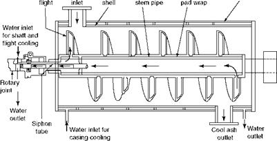
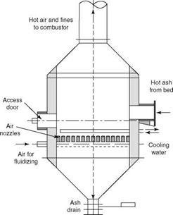
• A water-cooled ash screw cooler, shown in Figure 12.18, is a good solution for a dry ash discharge that is environmentally more acceptable. Ash from the bed is drained into a screw whose flights, shaft, and casing are all cooled by softened water of high quality.
|
Front Hot ash Inner Hollow Outer twin Outer shell
|
As the incoming ash is at —850°C normal bearing cooling water may not be adequate. When good-quality cooling water is not available, a closed loop is adopted. The heated water is cooled in a heat exchanger (HX) with the help of plant bearing water and the cooled water is returned to the system. When the plant cooling water is of acceptable quality, an open system with no heat exchange is adopted.
Ash is usually cooled to —80°C, and discharged in a dry manner in trucks. Screw coolers are then —6 to 7 m long. They are significantly shorter when higher ash temperatures such as 150°C can be tolerated. Screw coolers have a capacity limitation of —6 tph, making multiple screws essential for larger boilers. At least one ash discharge is essential for every
10 m2 of bed surface for effective draining. Ash screws are required to below the boiler at all times. This makes the boiler a little taller.
A screw cooler is essentially a screw conveyor with water cooling of the casing, shafts, and the flights to make it withstand the heat and also cool the ash. It has an intricate construction because
• There is a need for a rotary joint between the stationary water pipe and the rotating shaft.
• A heavy-duty pipe with a wrap-around plate over which the flights are welded addresses expansion issues.
• All the flights must be double-walled to create a hollow space for water flows.
• The ends of the flights must be covered with hard alloy to withstand erosion.
Screw coolers are expensive and need good-quality water, but they are compact and elegant. In comparison, FBACs tend to be cheaper but the refractory maintenance issues are present.
Fluidized Bed Ash Coolers. The FBAC, shown in Figure 12.19, is static and needs no great care in operation other than refractory maintenance. When there is high ash in coal and heat recovery makes sense, FBAC is a better choice.
|
|
|
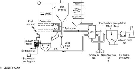
Ahlstrom-type hot cyclone circulating fluidized bed combustion boiler with fluid bed ash coolers, fly ash recirculation, and first-pass superheater with omega tubes. AH, airheater; ECON, economizer; PA, primary air; RH, reheater; SA, secondary air; SH, superheater. |
An FBAC is a bubbling bed heat exchanger with in-bed cooling water coil similar in construction to FBHE. Unlike the uniform nature of cyclone ash, here the ash is of variable size and tends to sinter when defluidized. The fluidizing air gets heated after cooling the ash to —200 to 250°C. This hot air is injected into the furnace. As ash needs to slide into the bed, the FBAC is placed alongside the combustor. This arrangement permits lowering of the combustor.
Screw cooler or FBAC. Each manufacturer has its own system. Typically, screw cooler is the choice when ash is low, whereas FBAC is better when ash is high in coal. Heat can also be recovered usefully by an FBAC.
Salient Process Parameters of CFBC Boiler
Figure 12.20 illustrates the hot cyclone design with no FBHE but with SH in first pass (where required), as developed by Ahlstrom. The Lurgi is shown in Figure 12.12. The process parameters of both types are tabulated in Table 12.6.
The new commercial CFBC boilers could
1. Meet the tough environmental standards due to cool and clean combustion
2. Demonstrate multifuel capability
3. Burn difficult and even unburnable fuels due to the reserve of hot solids in the bed and combustor
In comparison to the well-established PF firing, the early CFBCs were deficient in the following areas:
1. Higher auxiliary power consumption (marginally)
2. Heavy refractory maintenance
3. Unusually long start-up and shutdown times
4. Poor load dynamics
5. Lower reliability mainly due to erosion of tubes and refractory
6. Scale-up
Salient Process Parameters of Full-Circulation Circulating Fluidized Bed Combustion Boilers
Fuel Top size Mean Sorbent Top size Mean Combustor Velocity Particle size Temperature Pressure drop Recycle rate Performance Carbon loss
Ca/S for 90% SO2 capture
SO2
CO
NO,
6-8 mm 0.5-1.0 mm
1.0 mm 0.2 mm
3.5-7.0 m/s (—11.5 to 23 ft/s)
0.1-0.3 mm
800-950°C (1470-1740°F)
1000-2000 mm w. g. (—40 to 80 in. w. g.) 10-100:1
1-2%
1.8-2.5
<100 ppm dv <100 ppm dv <100 ppm dv
Except for auxiliary power all other problems arose from the unusually high amount of refractory in the boilers.
The CFBC boiler is the real challenger to PF. It may not be able to eclipse the PF entirely, but it has managed to edge out PF, up to 100 MW for conventional fuels and to much larger sizes, up to nearly 500 MW, for difficult-to-burn solid fuels. CFBC boilers are
• Industrial types up to 100 MWe (400 tph)
• Reheat-type utility boilers for >100 MWe
Besides the expensive hot cyclone, the second-generation designs such as cold cyclone, compact, and U-beam are available in industrial range. For large utility boilers, full — circulation types give a more compact arrangement. Also, only Ahlstrom and Foster Wheeler build utility boilers with the improved technologies. The expanded bed designs can also meet the utility boiler requirements.
Present-day designs can be broadly categorized as follows:
1. Full circulation
A. Hot cyclone design
B. Compact design
2. Expanded bed
A. Cold cyclone design
B. U-beam/no-cyclone design
Full-Circulation CFBC Boilers
Full-circulation designs employ high velocities and high ash recirculation with no distinct bed and have high fan power. Hot cyclone is the early design of both Ahlstrom and Lurgi, and several boilers were built on this principle, even to large sizes. AE&E-Lentjes and
|
|
|
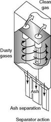
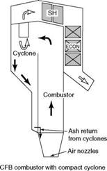
FIGURE 12.21 Compact separators. CFB, circulating fluidized bed; ECON, economizer; SH, superheater. (From Foster Wheeler Corporation. With permission.) |
 Alstom continue with hot cyclone design, although the velocities and recirculation ratios have been reduced with attendant lower power.
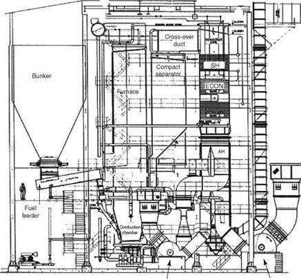
Foster Wheeler Corporation produced hot cyclone CFBC boilers, with the difference that the cyclone was made not of steel shell but of membrane panel, with either water or steam cooling, to reduce the refractory problems. After the acquisition of Ahlstrom, FWC developed a new "compact" design. Essentially, the cyclone is redesigned in an octagonal or rectangular shape and directly attached to the combustor wall, doing away with cyclone inlet and discharge legs and return pipes and seal pots, as shown in Figures 12.21 and 12.22. The cyclone is now made of membrane panels with water inside. The refractory is therefore reduced to a mere lining.
The problems listed in Section 12.5.3 that plagued early CFBC boilers, have been largely addressed. However, the disadvantage of this design is obviously the cyclone efficiency, which makes it more suitable for high-ash, high-volatile fuels.
Expanded Fluidized Bed Combustion Boilers
Basically the expanded bed boiler falls between the bubbling and the full-circulation FBC systems. Operating midway in the fluidization regime at —4 m/s bed velocity, the expanded bed concept combines the advantages of
• Simplicity and lower power of BFBC
• Higher efficiency and flexibility of CFBC
• Minimum refractory in boiler:
1. By cooling the gases to —400 to 500°C in the first pass and employing a steel cyclone (with protective refractory), making it a cold cyclone design.
2. By replacing cyclones with inertial separators and directly dropping the ash into the furnace.
The possible reduction in combustion efficiency due to less ash recirculation is made up by recirculation of ash from the first field of ESP.
The comparison in Figure 12.23 captures the details and the differences of the three designs. It compares all the three technologies in terms of (1) bed velocities, (2) heat release
|
PA fan FD fan FIGURE 12.22 Typical 100 tph compact-type industrial boilers. AH, airheater; ECON, economizer; FD, forced draft; PA, primary air; SH, superheater. (From Foster Wheeler Corporation. With permission.) |
Rates (in plan area), and (3) power consumed. Approximate evaporation limits are also indicated. As the bed velocities increase
• There is an increase in auxiliary power.
• There is an increase in heat release.
• Slender boilers have smaller foot prints.
• Higher boiler capacities are possible.
Full-circulation CFB consumes some 60% more power and delivers a 40% higher heat release. It is easy to understand why the hot cyclone is more competitive despite the advantages of the expanded bed designs.
Cold cyclone CFBC technology was originally developed by Deutsche Babcock after building both BFBC and CFBC boilers. This technology was, in the 1990s, acquired by Lurgi and later passed on to Lentjes. It consists of a conventional tower-type boiler with a CFB
|
Fluidized Bed Combustion 543 |
|
Expanded FBC |
|
If |
|
<150 1.8-3.0 ~1.5 |
|
Capacity (tph) Velocity (m/s) Heat (MW/m2) Aux. power (kW/MW/h) ~14 |
|
850- 900°C |
|
Limestone |
|
O O Bed |
|
Coil |
|
Њ5=5: |
|
850°C |
|
||
|
||
|
||
|
||
 |
||
|
||
|
||
 |
||
|
||
|
||
![]()
Combustor at the bottom of the first pass and a cyclone between the first pass and the second pass. It can be viewed as
• A BFBC boiler with in-bed coils shifted to the top of freeboard
• A CFBC boiler with FBHE coils shifted from FBHE to first pass
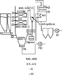
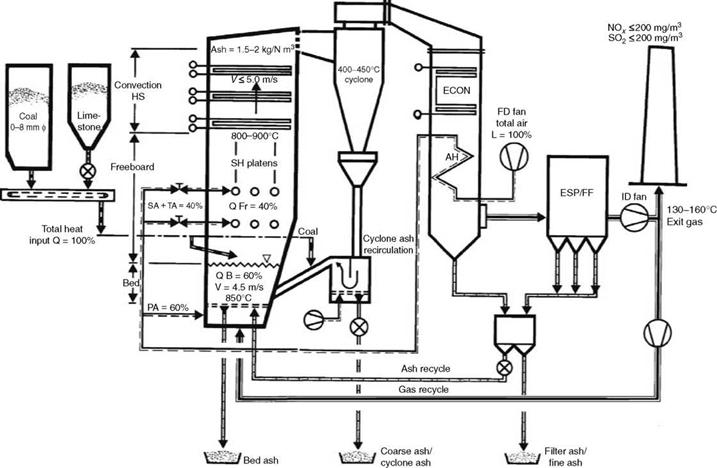
Figure 12.24 shows a cold cyclone boiler.
The salient features are shown in Table 12.7 and Figure 12.28.
The advantages of cold cyclone design over the full-circulation CFBC are as follows:
• Lower fluidizing velocity and hence lower FD fan power.
• Massive 80% reduction in refractory—only 50 mm in cyclones and none in second pass.
• A very steady bed temperature and a little variation across the bed because of the controlled recirculated cold ash.
• Cold start-up times of ~4 h (down from 10 h in full-circulation CFB).
• Only steel casing of the second pass, as gas enters at <450°C. No membrane panels.
The tower-type design of the boiler, also covered in Section 9.3.3.2, gives the following benefits:
• No tube bundles in gas turns to suffer erosion due to the centrifugal force of ash.
• For the bundles located in the first pass, the erosion is not present because
— The gas flow is normal to tube axis, which is nonerosive.
— Gas velocities are low at <5 m/s.
— Dust in gas is of <0.4 mm (a maximum particle size that can be suspended in a stream flowing upward at 4 m/s velocity).
— Erosion shields are carefully placed on the tubes to avoid wear.
— The first row of tubes facing the gases and carrying the load of all the tube bundles, called screen (evaporator) tubes, can be fully studded to avoid erosion as well as increase the HS.
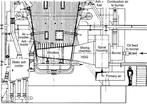
Hot gas generators (HGGs) are employed in cold cyclone boiler design for providing hot air during startup with oil. A HGG is a horizontal refractory-lined empty vessel with
Oil or gas burners on one end and hot gas discharge to the windbox on the other. Part of the PA is diverted into the circular burner of the HGG only during startup to burn oil and generate hot gas at 900°C (1650°F). The hot gas heats the bed positively from the bottom, until the bed attains the ignition temperature of the main fuel varying from 400 to 600°C (750-1110°F). As the bed is heated from the bottom (with very hot gas at 900°C), the bed heating is positive and rapid, which contributes to the shortening of start-up time of the boiler.
|
Fluidized Bed Combustion 545 |
|
|
|
TABLE 12.7 Salient Features of Cold Cyclone Circulating Fluidized Bed Combustion Boiler Design
|
With low refractory in the boiler and quick burning of fuel, the load rising is very fast in this design.
Figure 12.25 shows the lower combustor of a four-cyclone boiler, with HGGs attached to a windbox, where the fuel and air entry into the combustor from either side can also be seen.
When gas is to be used as the start-up fuel, duct burners are preferred to HGGs as they are lighter and more compact. Please refer to Section 10.3 for a description of duct burners.
Unlike heat recovery steam generators (HRSGs), the duct burners must be accommodated in narrow ducts that experience a lot of heat. Care is required in measuring the gas temperature properly at the center of the discharge duct and not at the edges, lest the operator continues firing the gas until the whole duct is damaged due to overheating.
Cold Cyclone Design versus Classical CFB Boilers
• The combustor bed is wider by —50% compared to full-circulation CFB due to less bed velocity.
• Although in efficiency and environmental parameters it matches full-circulation CFB, the speed of combustion is lower.
• Single-, double-, and four-cyclone executed designs cover a range of 40-400 tph or 10-100 MWe.
Larger boilers with six or eight cyclones reaching up to 700 tph have yet to be built.
In comparison to full-circulation CFB, cold cyclone design is very competitive due to
• Lower HS and less weight of pressure parts (PPs) because of HS in the first pass where heat is given by gas as well as solids
• Much less (—20%) refractory because of only 50 mm lining in the cyclone as against 500-600 mm of brick work.
|
FIGURE 12.25 Lower combustor of cold cyclone boiler with hot gas generators mounted on windbox. HGG, hot gas generator; SA, secondary air. |
• Start-up times to reach full load are between 3 and 4 h compared to 10-12 h due to a low amount of refractory.
• The corresponding oil consumption is about one-fifth of that in hot cyclone operation.
• A feed water top-up pump is not required. In hot cyclone design, it is necessary because water in boiler circuits evaporates soon after a shutdown due to the radiation of heat from refractory.
Table 12.8 captures the differences in detail.
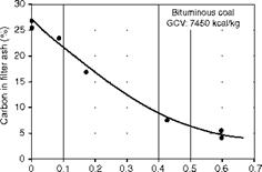
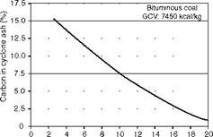
To improve the carbon burnup, ash recirculation from the cyclone and filter needs to be incorporated. The effect of the recycle ratio can be understood from Figures 12.26 and 12.27. Although they are specific to cold cyclone, they represent the phenomenon correctly. Quick — burning fuels such as lignite do not need filter ash recirculation, as the burning is complete. Similarly, high-ash coals also are not subjected to ash recirculation, as the fractional improvement in efficiency is not commensurate with the attendant erosion problems in ash lines and the additional power consumption.
Figures 12.26 and 12.27 depict the effect of ash recirculation of cyclone and filter ash in cold cyclone design for a typical bituminous coal having a GCV of 7,450 kcal/kg (13,410 Btu/lb)
|
Comments for Cold |
|||
|
Parameter |
Cold Cyclone CFBC |
Hot Cyclone CFBC |
Cyclone |
|
Boiler design |
Tower type |
Two-pass boiler |
First pass HSs receive |
|
With HSs in first pass |
With mostly HSs in second pass |
Heat from gas and dust |
|
|
Second pass |
Steel casing |
Membrane panel casing |
Simple and inexpensive |
|
Total heating |
Lower |
Higher |
First pass HSs very |
|
Surfaces |
Effective |
||
|
Fluidizing velocity |
3.5-4. 5 (~11.5 to 15 ft/s) |
4.5-7 (~15 to 23 ft/s) |
Need < 6 m/s on tube |
|
(m/s) |
Bundles |
||
|
Auxiliary power |
~15 |
~ 26 |
Lower FD fan pressure |
|
(kW/MWth) |
|||
|
Cyclone |
400-450 (~750 to 850°F) |
~850 to 900 (1560-1650°F) |
|
|
Temperature (°C) |
|||
|
Cyclone |
Small, maximum diameter ~3.5 m |
Large, maximum diameter ~8 m |
Due to low gas temperature |
|
Cyclone refractory |
50 mm castable |
~600 mm refractory and insulating bricks |
|
|
Ash recirculation |
10-12 |
10-100 |
Ash pipes small and |
|
Times |
Unlined |
||
|
Dust in combustor |
1.5-2 (~0.1 to 0.125 |
10-40 (~0.62 to 2.5 lb/N ft3) |
|
|
(kg/m3) |
Lb/N ft3) |
||
|
Bed temperature |
By cyclone ash |
By cyclone ash, fluid bed heat |
|
|
Control |
Recirculation |
Exchangers, gas recirculation |
|
|
Bed temperature |
Very steady across bed |
Bed temperature not as steady |
Bed is cooled by low — temperature ash. Fine control by gas recirculation possible. |
|
Tubes |
Normal in first and second passes |
Omega in first and normal in second pass |
|
|
Total refractory |
Small |
High by 4-5 times |
|
|
Refractory erosion |
Nil to small |
High to very high |
Low dust in gases and lower velocities |
|
Start-up time from |
3-4 h |
10-12 h |
Due to much less |
|
Cold |
Refractory |
||
|
Start-up oil |
5-6 |
~24 |
|
|
Consumption (t) |
|||
|
Feed topping-up |
Not required |
Required |
Less refractory, less |
|
Pump |
Heat |
|
TABLE 12.8 |
|
Comparison of Cold and Hot Cyclone Circulating Fluidized Bed Combustion (CFBC) Boilers |
![]()
|
FIGURE 12.27 Effect of filter ash recirculation on char. |
![]()
|
FIGURE 12.26 Effect of cyclone ash recirculation on char. |
![]()
|
Cyclone ash recirculation Filter ash recirculation |
![]()
|
FIGURE 12.28 Typical 100 tph cold cyclone design with two cyclones, siphons, and hot gas generators. AH, airheater; ECON, economizer; FD, forced draft; HGG, hot gas generator; ID, induced draft; PA, primary air; SA, secondary air; SH, superheater; TA, tertiary air. |
And —8% ash and —3% moisture. The higher the carbon in ash, the higher is the recirculation required. Recirculation is defined as the ash mass flow divided by the fuel mass flow. Cyclone ash recirculation is —50 to 100 in hot cyclone and compact design as opposed to a maximum of 20 in cold cyclone design. But filter ash recirculation and effect are similar.
The power of filter ash recirculation can be realized when carbon in filter ash is dramatically reduced from —25 to 5% with an ash recirculation as low as 0.6.
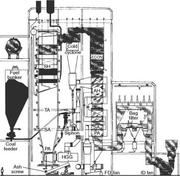
Figure 12.28 shows a two-cyclone industrial boiler with plain tube ECON and horizontal tubular AH as the back-end equipment. A bag filter is used for flue gas cleaning due to stringent pollution requirements. Ash recirculation from the filter is used for improving the carbon burnup. Boiler startup is with the HGG, when the fuel is oil. Bottom ash discharge is by water-cooled screws. Fuel feed and hot ash limit the number of openings in lower combustor and also heat the fuel with the contact of hot ash. Figures 12.25 through 12.28 have been adapted from publications of the former Deutsche Babcock.
No-Cyclone U-Beam CFBC Boilers
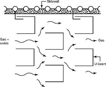
Studvik of Sweden promoted this technology in the 1980s. It was acquired by Babcock and Wilcox Company and developed further and commercialized. Steinmueller of Germany also built a few units with no cyclones. The constructional features can be summarized as follows (Figures 12.29 and 12.30).
|
Cumulative efficiency (%) 75 97.5 99.7 Component
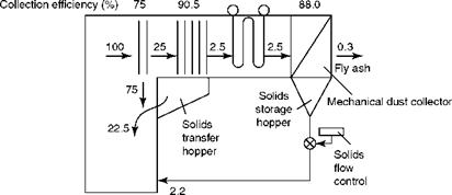
FIGURE 12.29 Solid distribution in U-beam boiler. (From Babcock and Wilcox Company, U. S.A. With permission.) |
|
FIGURE 12.30 Arrangement of U-beams. (From Babcock and Wilcox Company, U. S.A. With permission.) |
Features of U-Beam Type CFBC Boilers
• In U-beam design, a conventional bidrum or single-pass boiler is fitted with a CFB combustor at the bottom of the furnace and an inertial separator at the top in the same place as a vertical platen SH.
• The expanded bubbling bed, similar to cold cyclone design, has defined dense, primary, and disengaging zones. Overfire air is provided at the end of the disengaging zone.
• Furnace tubes are lined with refractory up to the SA and TA nozzles to prevent erosion and corrosion against the impinging bed material and the prevailing reducing conditions in the lower combustor, respectively.
• The SS 304 air nozzles used in this design are small and closely spaced (100 mm or 4 in. square pitching typically, i. e., 100/m2) nozzles of the same construction as BFBC.
• Fuel feeding is by gravity, at an inclination of 60-65° to horizontal, similar to cold — cyclone design, as the furnace is at a slightly negative pressure. This makes the system simple.
• Bed ash discharge is at the bottom of the furnace with 200 (8 in.) NB ash pipes. Screw coolers or static FBACs are employed for cooling ash before disposal. For most industrial boilers, two to four ash pipes are employed.
• Bed heating is by overbed burners or lances similar to a hot cyclone design. This tends to make a cold start a little slower as compared to a positive bed heating from below as in the case of cold cyclone.
• Division or wing wall HSs are provided in the furnace to cool the gases to the desired level.
• A two-stage dust collection is employed. U-beams perform primary collection at —97.5% efficiency, as shown in Figure 12.29. To match the collection efficiency of hot or cold cyclones, an MDC with efficiency of >90% is located after the BB or ECON in a cooler zone at an elevation suitable for pneumatic conveying of dust. The collectors are made of hard castings with hardness of 550 BHN to withstand erosion of dusty gases spinning at high speeds in excess of 20 m/s.
• Alternatively, ESP ash from the first field, where particles are —70 |jm, is taken.
• Return legs and L-valves used for returning the ash collected at the bottom of U-beams in the earlier designs are obsolete. Two sets of U-beams are located at the furnace exit where —75% of the solids are collected and rolled down over the rear wall. Four sets of beams are placed after a gap where 90% of the incoming solids are collected in a solid storage hopper with discharge onto the rear wall.
• U-beams, typically —8 m long, are made of ss such as TP 309H, TP 310H, or RA 253 MA, depending on conditions to withstand high temperature and force from heavy dust loads traveling at 6-8 m/s. RA 253 MA is typically used for pet coke application.
• SHs are pendant type, whereas ECONs are horizontal. The first row of ECON tubes is protected against erosion by suitable tube shields.
• The enclosure of the second pass is made of membrane wall as in hot cyclone design.
This internal recirculation (IR) of ash has dispensed with the return leg altogether, with a corresponding reduction in refractory and air blower for the L-valve. Ash recirculation rate is high. Bed temperature is controlled by regulating the return of cold ash from MDC.
Salient Process Parameters of U-Beam Type CFBC Boilers
The important process parameters of this design are tabulated in Table 12.9.
Advantages and Limitations of U-Beam Technology
• U-beam is the most compact, simplest, and most conventional of all CFBC boilers.
• It has the unique capabilities of retrofitting a PF boiler, as no cyclones are needed.
• The combined pressure drop of U-beams and MDC is —100 mm wg as against —170 mm (7 in.) wg in a cyclone. The fan power is the least.
|
TABLE 12.9 Design Features of U-Beam Technology
|
• With no return leg and practically no refractory in the furnace the total refractory in the boiler is minimized to —10% of that in full-circulation CFBC boilers.
• With least refractory, the boiler load response is very good.
• Wide and seamless turndown of 20-100% without auxiliary fuel is possible.
• Quick startup from cold of <6 h is achievable.
The bed temperature control is the most critical parameter in this design. With no positive control on the return ash from primary collector, all ash from U-beams flowing along the rear wall and bed temperature control dependent on the fine ash from MDC, a steady bed temperature is somewhat difficult to achieve. Fine ash does not stay in the bed long enough to provide effective cooling. Overheating of bed is dangerous because it leads to overheating of U-beams. If the beams alter shape or go out of alignment, the ash collection is reduced, leading to a further rise in temperature. Not enough units are running to establish the reliability of the design principle fully (Figure 12.31).


 11 сентября, 2013
  admin
admin 
 Опубликовано в рубрике