After being duly treated and deaerated, water gets pumped into the boiler as FW, which is heated in the ECON until it reaches the drum. Boilermakers and institutions responsible for water standards in various countries have evolved standards for FW and boiler water over the years, which, if maintained without any lapse during operation, would ensure trouble-free and long life. Table 4.2 gives typical recommended general limits for boiler FW by American Society of Mechanical Engineers (ASME). These recommendations cover the drum water limits as well. Each leading code, such as BS and DIN, has its own recommendations similar to ASME. It is to be noted that depending on the type of boiler, furnace heat flux, and the metallurgy adopted, the limits are further modified by boilermakers for a particular boiler. It is then the responsibility of the station chemist to ensure that the FW quality as specified by the boilermaker is strictly adhered to.
These points regarding FW are to be followed:
• The impurities should be so restricted that the limiting values in boiler water are achieved without excessive blowdown.
|
TABLE 4.2 ASME Guidelines for Water Quality in Modern Industrial Water Tube Boilers for Reliable Continuous Operation
|
• Where spray attemperation is employed, silica and solids should be as low as possible. Total solids should be <3 ppm to prevent deposition in SH and <0.1 ppm with austenitic section in SH.
• Spray water silica limit is <0.02 ppm when the boiler is feeding a turbine.
• The dissolved O2 obtained by physical deaeration must be invariably supplemented by chemical O2 scavenging. Na2SO3 can be used in boilers operating up to 125 barg and where there is no spray attemperation.
For other cases, N2H4 is used. It should be remembered that hydrazine is toxic and hence prohibited in hospitals and food manufacturing industries where steam may come in contact with food or beverages.
• pH should be within the range of 8.5-9.2 with Cu alloy FWH and 9.2-9.5 with steel FWH.
Some major impurities found in FW and their impact on various boiler surfaces are given in Table 4.3.
As steam gets separated from the boiler water, the impurities are left behind, and the boiler water attains a reasonably high level of concentration of impurities and chemicals, which needs to be controlled. This is in order that the
1. Carryover of minute amounts of water particles is restricted by not allowing priming and foaming to take place in the drum.
2. Solids inevitably carried over by the water particles are only in miniscule amounts.
There are established guidelines, such as the ASME recommendations, for efficient use of boilers and piping evolved over a long time by both boilermakers and users. ABMA also provides guidelines that are essentially the same as ASME’s (Table 4.4).
TABLE 4.3
Major Impurities in Feed Water and Problems
|
Feed |
Condensate |
|||||
|
Item |
Form |
Source |
System |
Economizer |
Boiler Superheater |
Turbine System |
|
CaCO3 |
Sludge |
Ca hardness |
X |
|||
|
Scale |
Ca hardness |
X |
X |
X |
||
|
CaSO4 |
Scale |
Ca hardness |
X |
|||
|
CaSiO3 |
Scale |
Ca hardness SiO2 |
X |
|||
|
CaPO4 |
Sludge |
Ca hardness |
X |
|||
|
Scale |
Ca hardness |
X |
X |
X |
||
|
Mg(OH)2 |
Sludge |
Mg hardness |
X |
|||
|
MgSiO3 |
Sludge |
Ca hardness SiO2 |
X |
X |
X |
|
|
Acid Cl |
Solution |
Cl |
X |
|||
|
Fe oxide |
Sludge, Scale |
Corrosion Products |
X |
|||
|
SiO2 |
Scale |
SiO2 |
X |
X |
||
|
Oil2 |
Soap and oil bound sludge |
Contamination |
Xx |
X |
||
|
O2 |
Corrosion Products |
Feed water |
X |
X |
Xx |
X |
|
CO2 |
Corrosion Products |
Free CO2 from CO3, HCO3 |
X |
X |
X |
|
TABLE 4.4 |
ABMA Standard for Boiler Water Concentrations for Natural Circulation Boilers for Minimizing Carryover
|
Drum Pressure |
Boiler Water |
|||
|
Total Silicaa |
Specific Alkalinity |
Conductance |
||
|
In barg |
In psig |
(ppm SiO2) |
(ppm CaCO3) |
(^n/cm) |
|
0.0-20.7 |
0-300 |
150 |
700 |
7000 |
|
20.7-31.0 |
301-450 |
90 |
600 |
6000 |
|
31.0-41.4 |
451-600 |
40 |
500 |
5000 |
|
41.4-51.7 |
601-750 |
30 |
400 |
4000 |
|
51.7-62.0 |
751-900 |
20 |
300 |
3000 |
|
62.0-69.0 |
901-1000 |
8 |
200 |
2000 |
|
69.0-103.5 |
1001-1500 |
2 |
0 |
150 |
|
103.5-138 |
1501-2000 |
1 |
0 |
100 |
A This value will limit the silica of the steam to 25 ppb as a function of selective vaporization of silica. Specific conductance is unneutralized. 2 ppm = 1 mg/N m3.
The purpose of conditioning treatment is to
1. Prevent scale formation inside pressure parts (PPs) from small amounts of hardness and other impurities of FW
2. Remove traces of dissolved O2
3. Maintain correct chemical balance in boiler water
The four main types of conditioning treatments adopted are as follows:
1. Phosphate-hydroxide treatment (conventional phosphate treatment) for drum pressures up to 70 bar
2. Coordinated phosphate treatment for pressures >70 bar
3. Chelant treatment for pressures up to 100 bar
4. Volatile treatment for pressures >140 bar
Conventional Phosphate Treatment
This treatment is most popular with industrial boiler plants as it suits pressures up to 70 bar and consists of
• Maintaining a pH of 10.5-11.2 with excess OH
• Converting the hardness constituents as flocculent precipitate, which is blown off
Orthophosphate residuals are maintained between 20 and 60 ppm as PO4 and hydrate alkalinity between 200 and 400 ppm as OH. At pressures >70 bar, these alkalinity levels are too high; hence, this method is unsuitable for boilers operating in this condition.
Coordinated Phosphate Treatment
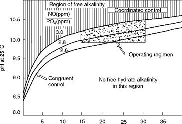
In this treatment, no free caustic is maintained. Phosphate concentration as a fixed relation to boiler water pH is maintained. A molar ratio of 3:1 for Na+:PO3- is achieved for trisodium phosphate. If the molar ratio is kept at 2.6:1 (congruent phosphate conditioning), free NaOH does not form. The treatment chemicals are a combination of tri — and disodium phosphates. This treatment is suitable for boilers operating over 70 bar, as caustic corrosion is a serious concern at higher pressures.
The pH correction is done by altering the ratio of tri — and disodium phosphates. To increase the pH, trisodium phosphate is increased. Figure 4.7 illustrates the two regimens of treatment.
|
Orthophosphate concentration (ppm) FIGURE 4.7 Operating regimes for coordinated and congruent treatments for pressures from 70 to 110 bar. |
Organic agents react with residual divalent metal ions, Ca, Mg, and Fe in the FW to form soluble complexes, which are then removed by blowdown. Chelant treatment provides much cleaner boiler surfaces than precipitation treatment. Chelant treatment requires FW to be low in hardness (<2 ppm), which demands softened or DM water. Sodium salts of ethylene diamine-tetraacetic acid (EDTA) and nitriloacetic acid (NTA) are the two most common boiler water chelating compounds. Both the chelants are susceptible to thermal degradation and hence are fed to the FW. Since O2 hastens the degradation, the FW should be free of O2 before the chelants are added.
Chelant treatment is capable of providing good scale-free internal surfaces. But the inability to accurately test and control free chelant residuals can lead to overfeeding and subsequent corrosion. Presence of O2 in boiler water can also lead to excessive chelant corrosion. It is normal, therefore, to add phosphates to the extent of 15-30 ppm to prevent chelant attack during upset conditions caused by HX leakages. Chelant treatment is popular up to a pressure of 100 bar.
For boiler operating at pressures >140 bar, a pure water approach is adopted in which the FW is rendered contamination-free by employing an all-volatile treatment (AVT). All control is directed to FW quality. Corrosion and deposition are kept under check by elimination of all chemicals likely to cause problems, namely, hardness, salts, alkalinity, and so on. The operation is with zero solids in boiler water, which naturally gives pure steam output. If there is contamination of FW, there is a possibility of excessive corrosion as the buffering ability of the boiler water is absent. Also the deposits are much harder to remove. Only NH3 and N2H4 are added to the boiler water for pH control between 9.2 and 9.4.
Anionic polymers are used for sludge conditioning because of their easy removal. The polymer molecules wrap around the suspended boiler sludge, which enhances the fluidity. They also aid in inhibiting scale formation and removing the existing scale. Lignin is the least effective controller.
Integrated with the boiler water conditioning, blowdown is carried out to discharge the sludge and maintain the desired balance of chemicals. There are two blowdowns in a boiler.
1. Intermittent blowdown (IBD) is periodically carried out by specially designed full opening valves for removing suspended solids and sludge in boiler water. It is most effective when operated for brief periods with valve at full open condition, typically once in a shift. It is also called dirty blowdown because it contains sludge. No heat recovery is possible.
2. Continuous blowdown (CBD) is achieved by finely regulated micrometer valves and measured by an orifice plate for controlling total dissolved solids (TDS) in boiler water in lower pressures and silica in higher ranges. Heat recovery is possible.
CBD as percentage of MCR =——- :—————- :—s c>lids in FW,——————- ———-
R ° maximum permissible solids in boiler water — solids in FW
In addition to the dissolved O2, FW invariably contains CO2 and traces of NH3. The latter is insufficient to cause problems of overconcentration or prevent CO2 reaction with steam in the formation of carbonic acid in condensate. Natural alkalinity from NaZ treatment is the source of CO2.
Cyclohexylamine, morphiline, and diehanolamine are most commonly used amines in industrial practice for corrosion inhibition in the after-boiler section by neutralizing the condensate pH, whereas it is performed by NH3 and NH4 in utilities. A filming amine, normally octadecyclamine, is commonly used alone or in combination with the neutralizer. Volatilization of these amines at different points in the system gives a wider protection of the steam and condensate lines. The condensate pH is typically maintained in the range of 7.5-85.
Filming amines are used to establish a continuous protective film over the after-boiler surfaces, which prevents the contact of potentially corrosive steam and condensate constituents with the interiors of system components. They are added directly into the steam headers. A filming amine program is less costly than a neutralizing amine program.
In NH3 and N2H4 combination, the hydrazine scavenger breaks down to form NH3 and N2 and serves as a neutralizer, counteracting the carbonic acid formed when CO2 dissolves in condensate. NH3 and N2H4 treatment
• Is an all-volatile approach, mainly suited for high-pressure boilers
• Minimizes the introduction of organic compounds into the system
• Affords condensate pH control at a minimal cost
However, excessive NH3 leads to corrosion due to enhanced pH of the condensate.
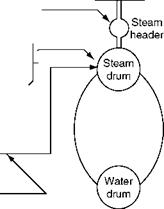
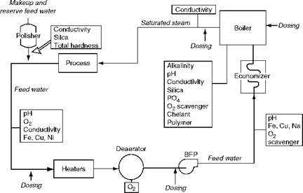
Chemicals are dosed in the boiler circuit at two points (Figure 4.8), and measurements done at several places (Figure 4.9):
1. Before the feed pump at low pressure
2. Into the drum at high pressure
A. Low-Pressure (LP) dosing. LP dosing of chemicals, upstream of boiler feed pump (BFP) at the discharge of the deaerator, is done with a view to condition the FW to the required levels before the FW enters the ECON or drum. The external water treatment followed by deaeration would have made the FW nearly conform to the limits. LP dosing is done for
I. pH correction by dosing NH3
Ii. O2 scavenging to remove the final traces by dosing Na2SO3 usually for pressures <70 bar and N2H4 for pressures >70 bar (sometimes up to 125 bar)
Iii. Boiler water conditioning by chelant dosing if chelant treatment is adopted
Iv. Boiler water conditioning by NH3 and N2H4 dosing if AVT is adopted after boiler protection by amine dosing
B. High-Pressure (HP) dosing. HP dosing of chemicals directly into the steam drum is done to
I. Raise and maintain the pH of boiler water to prevent corrosion by dosing NH3
Ii. Form soft sludge of the suspended solids that can be intermittently blown down (blow off) by dosing phosphates
Iii. Condition sludge for better and easier removal by dosing sludge conditioner
Iv. Prevent buildup of foam inside the drum, which contributes to increased carryover by dosing antifoamants.
|
Sulfite/ Hydrazine
|
|
Filming amine > neutralizing amine} Poly/ortho PO4 sludge conditioner neutralizing amine antifoamant |


|
Feed pump Ђ7: |
![]() Chelant polyphosphate sludge conditioner neutralizing amine antifoamant
Chelant polyphosphate sludge conditioner neutralizing amine antifoamant
FIGURE 4.8
Chemical dosing in a boiler plant.
|
FIGURE 4.9 Dosing and measurement points. |


 22 августа, 2013
  admin
admin 


 Опубликовано в рубрике