Boiler Classification by Firing
Oil- or Gas-Fired Boilers
Oil — and gas-fired boilers are burner-fired and are amenable to extensive standardization because of a fair degree of uniformity of the fuel characteristics. The quick and relatively clean burning nature of the fuels makes them compact and suitable for full or part shop assembly, as in package or field-erected boilers, respectively.
Package Boilers
Package boilers are available for capacities up to 250 tph, with horizontal gas flow, bottom support, short drum centers, and extremely high heat release and absorption rates. These features allow such boilers to be compact and easily transportable on trailers or barges. Because of the horizontal gas flow, the package boiler design is more amenable to firing clean fuels such as gas and number 2 oil. One to four burners are always mounted on the front wall of the furnace. The furnace is arranged parallel to the drums and convection bank. Package boilers are shop assembled and sent to site where they are unloaded on a leveled, cemented floor requiring minimum foundation work. In developing countries, where transportation is expensive and labor costs for erection are low, the package boilers are often field erected with shop-made modules.
Field-Erected Boilers
Bidrum bottom-supported boilers for power and process steam are extensively standardized for capacities up to 450 tph. The flue gas flows up and down, permitting dusty and fouling oils and gases to be fired in these boilers. The burners are mounted on the front wall of the furnace arranged normal to the axis of the drums and convection bank, unlike in the package boilers where the furnace is set parallel to the drums. The modular designs of these boilers permit economical manufacturing and quick erection.
Single-drum design for oil and gas is the preferred configuration of many customers. Low water holding, less weight, and drainable SH in these boilers enable quick starts and shutdowns as required in two-shift operations. These boilers can be bottom supported for capacities up to 100-150 tph and top supported for larger sizes. There is a great flexibility in arranging the burners in these designs. They can be roof, floor, and sidewall or front wall mounted, depending on the desired SH characteristics.
All these boilers are more extensively dealt with in Chapter 10.
Stokers, which were workhorses, have been severely affected by the rise of bubbling fluid — ized bed combustion (BFBC) boilers and the tightening of pollution norms on both SOx and NOx. They can be classified as
• Dumping grate stokers
• Chain grate stokers
• Spreader stokers (SS)
• Pulsating/reciprocating grates (PGs/RGs)
Bidrum boilers are the industry standards for pressures up to —90 bar and the singledrum boilers for higher pressures of up to 150 bar. Bottom support is possible and economical up to —40 to 60 tph. Stoker-fired boilers are more elaborately discussed in Chapter 11.
Dumping Grates
Dumping grates are used to burn fuels like bagasse and occasionally low-ash coal where steam pressure fluctuations and loss of green fuel during the stoker dumping periods are acceptable. The combination of suspension (with —40 to 60% of heat release in furnace) and grate firing makes the dumping grates release much higher heat than gravity-fed chain grates. Dumping grates are very simple and inexpensive. No return strands make them very light, cheap, easy to maintain, and compact. Dumping effects get smoothened out as the number of grates increase in a boiler. Reasonably high heat-release rates, of —70 to 80% of traveling grates, are achieved with bagasse and similar uniformly sized biofuels. Dumping grates are unsuitable for firing coal of medium-to-high ash or fuels with some clinkering tendencies, as there is no automatic discharge from the grates. Bagasse-fired boilers as large as 150 tph have been built with multiple dumping grates.
Chain Grate Stokers
Chain grate stokers have gravity feeding and burn fuel in a quiescent state. The fuel burns substantially on the grate, with only the volatiles burning in suspension. Burning rates are low and burning is slow. The grate and the furnace are large. As there is no agitation of the fuel bed to expose more surfaces, the ash in the fuel has to be low (<15%). This type of firing is yielding to SS and BFBC boilers.
Spreader Stokers
Spreader stokers (SSs) are the most versatile and feature
• The highest heat-release rates
• Continuous ash discharge
• Very good load response due to suspension firing
• Fully automatic combustion control
• Exceptional fuel flexibility
• Very good multifuel firing capability
However, they suffer from certain limitations, such as they cannot
• Burn high-ash coals (>35% ash) efficiently because unburnt losses are high
• Effectively burn lignites of high moisture (—55% and above)
• Deal with high sulfur in coal
• Produce low NOx combustion to meet the emerging norms BFBC boilers have largely displaced them with their
• Superior low-temperature combustion technique (with the resultant low NOX)
• In-furnace desulfurization (making high-sulfur coals burn easily)
• Greater versatility with high-ash and inferior coals
• Practically no moving parts, making the operation and maintenance very simple
BFBC has progressively pushed SS firing to the burning of various biofuels. Biofuels have no sulfur and burn at low temperatures due to the high moisture in fuels. Such fuels do not lend themselves to burning in fluidized bed combustion (FBC) boilers satisfactorily and easily. Bagasse and biofuel burning is still an area where spreaders prevail.
Pulsating or Reciprocating Grates
Pulsating or reciprocating grates are ideally suited for high-moisture fuels like municipal refuse or very light biofuels. The reciprocating action of the grate bars helps in uncovering the fresh fuel and admitting air, thus improving the combustion efficiency. As the fuels are usually gravity fed on the grates, the heat release rates do not match those of the spreader since there is no suspension firing. Single or multiple grates in series can be used, depending on the fuel moisture. For municipal refuse, where fuel moisture can exceed 70%, a steeper grate is used for fuel drying, followed by a combustion grate at a reduced inclination. Continuous ash discharge, single strand of grate with no return section, and somewhat light construction are positive features of the PG. The sporadic agitation of the fuel bed on the grate, however, can contribute to clinker formation with coal. The reciprocating action of the grate bars in a PG may not be able to push and discharge the big clinker into the ash pit, unlike the traveling grate that carries it positively. The clinker, when it grows large enough to straddle two grate bars, merely rocks due to the reciprocating action, but does not roll down. This prohibits the grate from firing coals with medium and high ash.
Fluidized Bed Combustion Boilers
Characterized by low-temperature combustion and in-furnace desulfurization, an FBC boiler is a genuine breakthrough in combustion technology. Commercialized in the late 1970s in response to the tightening air pollution norms and escalating oil prices, the FBC boilers firmly established themselves by mid-1990s.
There are two types of atmospheric FBC boilers—BFBC and circulating fluidized bed combustion (CFBC) boilers, both of which are discussed in detail in Chapter 12.
Bubbling Fluidized Bed Combustion Boilers
Bubbling fluidized bed combustion boilers use evaporators and sometimes SH bed coils to contain the combustion temperature of the bed. The air velocities employed in the bed are between 2 and 2.5 m/s at MCR to expand the bed to —1200 mm. At reduced loads, the minimum velocity required for fluidization of 0.8 m/s is always maintained. With abrasive fuels, the velocities are reduced to 1.5-2 m/s. The bed is composed of inert material or ash from coal and contains only —3% of fresh fuel. Limestone is added to the bed if coal needs desulfurization.
The heat release in the bed is comparable to that in SS, and hence the footprints of the two match closely. Likewise, with a residence time requirement of —2.5 s, the height of the BFBC boiler is only slightly lower than that of an equivalent SS-fired boiler. BFBC boilers, burning coal, are made to sizes as large as 150 tph, making them suitable for both process and power. With CFBC boilers in place to address the higher sizes, the BFBC boilers using coal are accepted up to 150 tph if the pollution norms are met. Large BFBC boilers of —400 tph are common in Scandinavia and other pulp-producing countries where the process produces large amounts of sludge with high moisture. Heat in the bed helps in combustion of such low GCV fuel with high moisture.
Circulating Fluidized Bed Combustion Boilers
Circulating fluidized bed combustion boilers employ ash for cooling the bed, together with staged combustion, to contain the bed temperature and produce lower emissions. The limestone and fresh fuel are added to the bed, which is composed of inert material or coal ash. The residence times are higher (between 4 and 5 s) and velocities of fluidizing air are also more (at 4-7 m/s), making the boilers very tall and slender.
Compared with the BFBC boilers, the carbon burn-up and desulfurization efficiencies are better, load dynamics are superior, and reliability is higher (as there are no worn-out or punctured bed tubes to replace periodically) in the CFBC boilers. The economical range of CFBC boiler is above 100 tph and is going as high as —1500 tph.
Circulating fluidized bed combustion boiler is seen as a potential utility boiler, rivaling PF, both in terms of efficiency and capacity. Many utility boilers are based on the CFBC principle, for fuels generally not burnable in PF firing with ease, such as petcoke with very high sulfur, anthracite, and so on. The fractionally higher power consumption and lower thermal efficiency of CFBC at the present stage of development places it unfavorably with respect to PF for conventional fuels and normal emissions. However, when fuels have higher S and the emission requirements are stringent, CFBC can work out to be more competitive with PF boilers having low NOx burners and gas scrubbers.
Pulverized fuel-fired boilers have the highest combustion efficiency at >99% carbon burn up, fractionally higher than CFBC boilers. The power consumption is lower in spite of the additional milling plant. In terms of fuel flexibility, multifuel firing capability, low NOx generation, and in-furnace sulfur capture, PF is much inferior to CFBC boilers. With over eight decades of service, PF boilers have burnt almost every type of coal across the world. In larger capacities, although PF is the choice in industrial range, CFBC is fast displacing PF. A conventional PF-fired boiler can be cheaper than the CFBC boiler for coal, but when low NOx burners are required along with reduced heat load and deSOx units are also to be added, the CFBC boiler works out to be more economical. It is a matter of time before PF firing exits industrial market altogether.
Pile burning is one of the early methods of firing, mainly developed for burning biofuel wastes such as wood bark, saw dust, wood shavings, bagasse, and so on. The method derives its name from the way the fuel is formed into a pile for burning. Horseshoe furnaces and pinhole grates (PHGs) are representative systems.
Horseshoe Furnace (Thick Pile Burning)
Fuel is gravity fed and dropped on the floor of the furnace in a conical pile. Hot air is admitted at three to four levels through air tuyeres formed in the brick walls surrounding the pile at temperatures ranging from 150 to 300°C. No air should enter through the floor, as it would escape from the edges of the pile and not participate in combustion. Combustion takes place on the sides of the pile. Brick walls arranged in a semicircular manner around the pile and the arches at the top of the pile have a very important role of radiating the heat of combustion. The furnace above the arches provides space for combustion of volatile matter (VM).
A bagasse-fired boiler would be fitted with two, three, or four refractory cells to generate —20, 30, or 40 T of steam, respectively. Each cell usually burns —5 T of bagasse and during cleaning the remaining cells in service would generate —20% extra. Heat release rates as high as —0.4 kg/m2 s (—300 lb/ft2 h ) of floor area for bagasse can be realized in these furnaces with cold air. Another 20% increase is possible with hot air. This combustion rate is approximately two to three times the combustion rate on grates with intensely high heat generation.
Pile burning used to be popular in rural environment or remote areas with limited operating skills and cheap fuel because
• Burning is simple and demands simple operating skills.
• Burning is vigorous but quiescent with no carryover to cause erosion of pressure parts (PPs).
• Fuel sizing is not a concern. Sizes up to 100 mm long can be tolerated.
• Fuel with moisture as high as 60% can be effectively burnt.
• 5:1 turndown is possible.
• Due to the large refractory and fuel inventory, temporary fuel interruptions do not affect the boiler.
Pile burning is almost obsolete because
• Combustion is inefficient and cheap fuels are unavailable.
• Load control is gross and is only possible by the variation of air. Fuel variation is not particularly effective as there is a lot of green fuel in the pile and plenty of heat in the massive refractory.
• Clinker formation is a recurring problem due to the uncontrolled nature of combustion and the high rates. The presence of hot refractory only worsens the problem.
• Refractory maintenance and repair are serious issues requiring periodical shutdown of the boilers.
• Ash removal is manual and there is loss of generation and reduced efficiency during deashing.
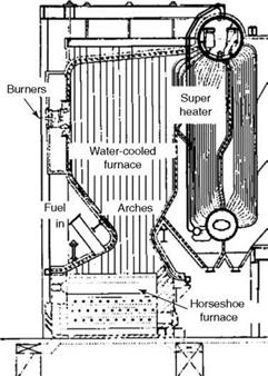
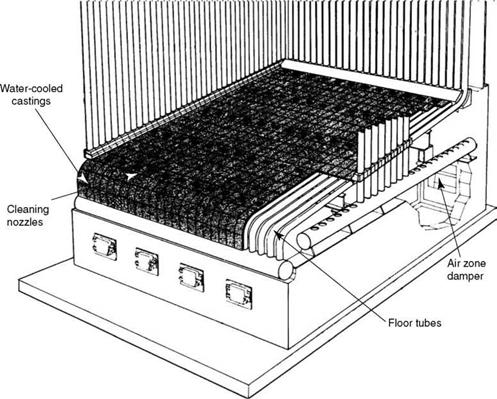
Figure 9.1 depicts a typical twin horseshoe furnace used for pile burning of bagasse. Figure 9.2 shows a furnace with water cooling. Pile burning combustors in the form of horseshoes are arranged below the conventional boilers.
Pinhole Grate (Thin Pile Burning)
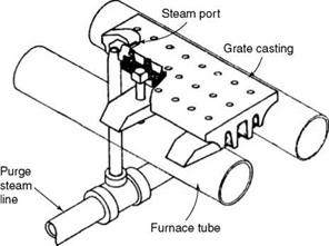
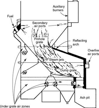
The name is derived from the fine pinholes that grate castings are provided with for air distribution (Figure 9.3). Pinhole grates (Figure 9.4) are stationary grates bolted tightly to the grate castings to the furnace floor tubes. Fuel is spread on the top by pneumatic spreaders in a thin pile similar to SS, and air is admitted from bottom through the fine
|
FIGURE 9.1 Horseshoe furnace with two cells. (From Babcock and Wilcox Company, U. S.A. With permission.) |
|
|
FIGURE 9.2
Horseshoe with water-cooled furnace.
|
|
FIGURE 9.3
Grate casting with cleaning port.
|
FIGURE 9.4 Pinhole grate assembly. |
Holes in the grate castings. Fuel can also be fed from the bottom in an underfed manner to form a pile when the quantities are small. To prevent the castings from overheating, they are bolted to the floor tubes tightly with no air film in between. The castings are usually shell molded. Close tolerances are achieved by grinding the mating surfaces. Under grate primary air (PA), secondary air (SA), and tertiary air (TA) are added to the extent of 20-30% to burn the volatiles in the furnace, similar to the overfire combustion in SS firing. Steam jets are provided to facilitate self-cleaning of the grate by blowing ash toward the rear hopper intermittently.
Design features of PHGs. Fuel is distributed on the grate by spreaders. PHGs share many process design features of SS firing. They use a combination of a thin pile burning of fuel on a grate inclined at —10° along with suspension firing, similar to the split combustion in the SS. There are some fundamental differences too.
• Pinhole grates are totally stationary and hence unsuitable for firing fuels containing ash which needs some method of removal and disposal for the sustenance of combustion.
• Pinhole grates are essentially for biofuels with low ash, which can be blown toward the discharge end of the grate easily. Steam jet blowing often is insufficient to keep the fires clean even with biofuels, and the ash has to be removed periodically by manual raking.
• The length of the grate is limited by manual raking and fuel spreading capability. Sufficient space in front of the boiler should be vacant for raking.
• As the grate castings are cooled by the floor tubes of the furnace, they remain substantially at the same temperature as the water walls and can accept high temperature of PA (—320°C/600°F) without the fear of overheating of castings or clinkering of ash. For higher air temperatures, grate castings are made of alloy steel.
• This feature of high PA temperature permits easy combustion of high-moisture fuels up to 55% on flat grates and 70% on inclined grates, while 52% is approximately the limit for SS.
• O&M is much easier as the system has no moving parts.
• I&C is simpler as there is no traveling grate.
• Efficiency and auxiliary power are approximately the same as in SS but there is reasonable steam consumption for ash blowing.
• Inclined water-cooled grates (IWCs) can handle higher fuel moisture and also unsized fuel as compared to flat grates or SS, as there are no spreaders to throw the fuel. Fuel travels by the steep inclination of the grate and has a longer residence time and intense radiation from the deep rear arch.
• Supplementary oil firing is needed for start-up and to deal with high moisture in fuels. In smaller sizes, charcoal firing can also be used for start up.
Design features of boilers equipped with PHGs.
• Boilers with PHGs are built to handle up to 200 tph of evaporation on biofuels such as bark and wood wastes. They are very popular in colder climates where there is an abundance of wood-based fuels.
• Heat release rates of the grate are similar to that of SS for biomasses varying from
1.6 to 3.5 MW/m2 or —1.35-3.0 mkcal/m2/h (500,000-1,100,000 Btu/ft2/h).
• Furnace-sizing parameters are also very similar. For efficient combustion and low carryover (which is a matter of concern for biofuels with low density), the furnace proportioning should be conservative. For biofuels with low to negligible alkali content in ash, which are used for generating steam at high temperatures, the following guidelines for furnace sizing apply.
— Volumetric heat release rates (VHRRs) should be 310 kW/m3 or <267,000 kcal/m3 (30,000 Btu/ft3).
— Furnace residence time calculated at furnace exit gas temperature (FEGT) and measured from the top of the fuel bed (reckoned to be 450 mm) to the centerline of the furnace aperture should be >2.5 s.
— Velocity of gases in the furnace at the above two conditions should be <5.5 m/s (—18 ft/s).
— Excess air can be 25% at furnace exit, about 10-15% lower than SS.
Volumetric heat release rate is generally chosen —10% lower than the limit as carryover can be very high due to low density of fuel leading to fouling or erosion problems. More evenly spaced high-pressure TA has to be provided in upper furnace to minimize carryover and complete the burning of fuel fines.
• In case of biofuels with high alkalies in ash, please refer to Table 11.6 and guidelines given in Section 11.5.4.
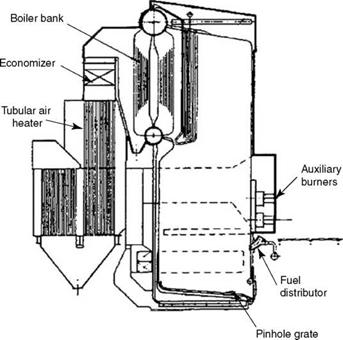
• With regard to the sizing of SH, boiler bank (BB), backend, and draft plant, the same principles as in SS apply (Figure 9.5).
|
FIGURE 9.5 Bidrum boiler with pinhole grates and fuel distributors. |
Pinhole grate versus SS.
PHGs have the following advantages:
• Lower excess air that can give fractionally more thermal efficiency
• Higher hot air temperature that helps to burn fuels with higher moisture
• No moving parts and hence low O&M costs
Because of the following disadvantages, PHGs have been overshadowed by SS:
• Other than oil and gas, practically no other auxiliary fuel can be burnt. Multifuel flexibility is limited.
• Dynamic response of the boiler is poorer.
• Manual raking is necessary and no continuous ash discharge is possible. Output may suffer.
Inclined Water-Cooled Grates (Semipile Burning)
Inclined water-cooled grates (IWCs) shown in Figure 9.6 share most construction and design details with PHGs. They are longer, expensive, and provide more residence time, and hence are used only when the moisture in fuel exceeds —55%. There are some basic differences in the way the fuel enters and burns in the IWC grates. Fuel is applied to the PHGs by means of spreaders. At high moistures, spreading is not possible. In the IWC
|
FIGURE 9.6 Inclined water-cooled grate for high-moisture biofuels. (From Power magazine. With permission.) |
Grates, fuel is admitted by gravity onto the grate, which is inclined at —47° to 48° to the horizontal. The fuel gets dried as it rolls down the inclination. Steam nozzles in the grate castings assist in this movement of fuel and ash. Thereafter it loses its VM, which burns in suspension. The fuel rolls further and gathers on the flat area at the end, where it forms a pile, and the fixed carbon (FC) burns vigorously. The rear wall is so shaped as to provide SA as well as direct radiant heat to the pile. In many units, a dumping grate is installed at the end so that dumping the ash after the pile burns down is easy and complete.
Classification by Number of Drums
About 50 years ago it was not uncommon to have three or even four drums in a boiler. More drums and large BBs meant more water-holding capacity and bigger thermal flywheels. Any sudden demand for steam could be met by a small drop in steam pressure, which would release steam from the latent heat of the boiling water in the drums and banks. With the advances in instrumentation and control, it is now possible to keep such sudden steam demands in check and reduce the number of drums to one or two.
Bidrum boilers are common for SOPs up to —70 bar and single drums are used beyond 100 bar. Bidrum boilers, which have convection tubes expanded in the top and bottom drums, are limited by the strength of expanded joints. Also at higher pressures, the large drum thicknesses interfere with good boiler dynamics. However, bidrums have the advantage of bigger water-holding capacity and hence
• An inherent ability to meet wider load fluctuations more readily. They are more forgiving for the operator and instrument sluggishness.
• They take more time for start-up and shutdown.
• For fuels like bagasse and wood, with a lot of heat in gases due to moisture, bidrum convection is necessary to dissipate the heat.
• Another positive aspect of bidrum design is that the flue gases are cooled due to the large heating surface (HS) in the bank to <450°C in most cases, permitting the use of plain carbon steel (CS) sheet for the second-pass enclosure. In single-pass boilers, membrane panel cooling is required instead, and is expensive.
Single-drum boilers are inevitable for higher pressures simply because the drums become too thick (150 mm and higher) above 100 bar, making it difficult to ensure a good tube expansion (Table 9.2).
• Single drums are preferred when faster response or two-shift operation is needed from the boiler.
• Single-drum boilers are usually lighter because of the absence of the water drum and BB. A steam drum is also nearly half the thickness.
• For SOPs lower than 45 bar, single-drum boilers usually need convection banks (with an upward slope of not <7° horizontal to induce circulation) to meet the
|
TABLE 9.2 Single versus Bidrum Boilers
|
Latent heat requirement. At lower pressures of 32 bar, forced circulation is necessary with the aid of pumps. The bidrum arrangement in such cases may be cheaper and simpler.
• The other main advantage can be the faster erection time. Unlike in a bidrum boiler where no major erection can start unless the drums and convection tubes are at site, in a single-drum boiler the furnace erection can proceed and drum can be erected later.
The usual arrangement is a single drum for pressures >100 bar and bidrums for <70 bar. There is a choice to adopt either of the two, which is made on case-specific basis.
Balanced Draft and Pressurized Firing
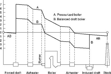
Combustion air must be forcefully admitted into the firing equipment via a forced draft (FD) fan. After combustion, the air turns into gas and must be evacuated by means of an induced draft (ID) fan in balanced draft operation where there is pushing of air and pulling of gas, and the furnace is maintained at near-atmospheric condition. There is, thus, a
Balancing of drafts.
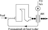
In pressurized boilers the FD fan pushes the air and the flue gas all the way to the chimney with no ID fan in the circuit.
• The boiler efficiency is slightly higher as there is no tramp air ingress into the setting, contributing to reduced stack losses.
• There is less O&M effort, as the fan and peripherals are eliminated.
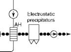
Pressurized firing is suitable for liquid and gaseous fuels. For solid fuels, balanced draft is more favored as there is generally a need for manual direct observation or intervention for which near-atmospheric conditions should prevail in the furnace. It must be considered that several very large OT boilers are in operation that employ pressurized firing (Figures 9.7 and 9.8).
|
|
|
|
|
|
|
|
|
|
|
![]()
|
|
|
FIGURE 9.7 Balanced draft and pressurized boilers. |
|
A CL |
|
2 □l |
|
O o |
|
Fan |
|
Air side |
|
Gas side |
|
Fan |
FIGURE 9.8
Typical draft-loss diagrams for pressurized and balanced draft boilers.


 31 августа, 2013
  admin
admin 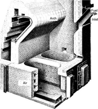
 Опубликовано в рубрике