Economizer surfaces transfer heat from flue gases to pressurized andsubcooled FW on its way to the drum. Heat transfer in an ECON is nearly entirely by convection, and hence the gas velocities are maximized consistent with pressure drop and tube spacing limitations. Coal ash in flue gas at temperatures <600°C is no longer sticky and hence fouling of tubes is not as much an issue as in SH. The ash is loose and does not form strongly adhering deposits and hence is easily removed by soot blowing. However, if there is a mixed firing of oil and coal, the ash can stick over the oil deposits that form on the tubes. The major concern is to reduce the surface and volume to optimize the space and cost.
• Usually smaller tubes with 38.1, 44.5, and 50.8 mm (1%, 1%, and 2 in.) ODs are chosen to increase the heat-transfer rate. 31.8 mm (1M in.) tubes are used in SC boilers and vertical HRSGs.
• Large-diameter tubes like 63.5 and 76.2 mm are adopted in vertical ECONs based on strength considerations.
• Close bending of tubes with radius of 1D or lower is also used most frequently.
• Care is taken to avoid a back pitch (along the gas flow) of 1.07-1.25 times the OD, via development of boundary layer, to avoid excessive draft loss and reduced heat transfer. Heat transfer can reduce by as much as 30% with this spacing.
• Optimum mass velocity for bare tube ECON lies between 5.4 and 6.8 kg/m2 s (4000-5000 lb/ft2 h).
Maximum permissible gas velocities and minimum tube spacing for ECONs are given in Table 6.6. Minimum spacing for bare tubes is 19 mm (3/4 in.), whereas for finned tubes, it is 13 mm (1/2 in.) between the edges of fins.
|
TABLE 6.6 Permissible Inlet Flue Gas Velocities and Tube Spacing (Perpendicular to Gas Flow) in Economizers
|
Water in ECONs should always flow upward to allow the steam bubbles to ascend smoothly. In the downward flow, steam bubbles can cause flow stagnation and disrupt the operation. In cases when downward flow is compulsory due to layout, adequate pressure drop is created by inserting ferrules for flow equalization.
Tube selection should not exceed 6 m/s (20 ft/s) of water velocity to avoid excessive pressure drop and also the erosion of tubes. A minimum water velocity should be maintained at —2 m/s (6 ft/s) for flow equalization. Likewise, the axial velocity in ECON headers should be <6 m/s (20 ft/s).
Economizer banks must be restricted to 1.8 m (6 ft) for effective soot blowing. A clear access of 600 mm (2 ft) is necessary for proper access and weld repair.
Economizers can be classified by design, construction, and arrangement, as given in Table 6.7.
Counter, Parallel, and Cross Flows
In most cases, ECONs are arranged in a counterflow mode to maximize the heat transfer and minimize the surface. Unlike in SH, there are no metal temperature problems that can be redressed by adopting parallel flow. Only in exceptional cases where there are constraints in arrangement, parallel flow may be adopted. In package boilers cross flow is adopted because the arrangement helps to save on the height of the ECON. Cross flow with gas flowing perpendicular to water flow is not as efficient as counterflow but it is better than parallel flow.
• Feed water outlet temperature should preferably be 30°C lower than the saturation temperature. This difference is known as the approach temperature that prevents steaming and water hammering. Also gas to water temperature is not narrowed down, which increases the HS without adding correspondingly to the water temperature.
• The economizer steams when the rise in water temperature is >67% of the difference between the saturation temperature and the ECON inlet. Simplicity and operational latitude demand a nonsteaming ECON.
|
TABLE 6.7 Classification of Economizers
|
• At times, this condition may in fact be beneficial to increase the ECON surface and generate some steam in it. Then the ECON outlet header should be located below the drum level. Care should be taken to avoid any loops or downward slopes in both ECON tubing and water piping from ECON to drum so that all the steam generated is constantly directed upward to the drum. Depending on the steam generation, it may be necessary to provide additional dedicated cyclones for separation. Usually 8% of steam generation is considered a safe limit, although there are cases of 20% steam generated on ECONs. The water treatment has to be very stringent.
Single and Multiple Tubes Per Loop
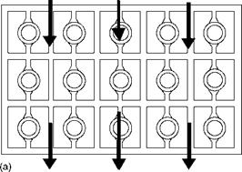
Carrying all water from the header by a single set of tubes placed side by side is a single tube per loop arrangement. A set of two tubes is called a two tubes per loop arrangement. Closed-loop bending of tubes can be avoided here. Also the two tubes are placed with a clear gap of 19 mm along the gas flow. This yields a very compact arrangement and reduces water velocities. Often, it is an easier way to pack —15% more surface within the same height of ECON banks without resorting to close-loop bends such as 1D or 0.8D (Figure 6.29a and b).
Cast iron (CI) stands up to both
• Internal corrosion due to dissolved oxygen among the ECONs because of the indifferent water treatment or lapses common in LP boilers.
• External corrosion due to sulfurous flue gases.
|
Gas in
FIGURE 6.29 (a) Single tube per loop. (b) Two tubes per loop. |
|
FIGURE 6.30 (a) Cast iron finned-tube economizer. (b) Cast iron gilled steel tube. (c) Helically finned tube. |
CI has limitations in withstanding pressures due to its porous structure. Up to a design pressure of 17.5 atm, finned CI ECONs (Figure 6.30a) make an excellent choice provided the quality of pressure castings is good. Their usage in modern boilers has drastically decreased, and steel tubes are overwhelmingly popular due to their strength and lightness.
• Taller fins lower efficiency of heat transfer
• Thicker fins increase efficiency of heat transfer
• Higher fin density increases HS and fouling
However, many boilers employ gilled steel tubes (Figure 6.30b) for even the highest pressures. Here the steel tubes, duly ground on centerless grinding machines, are shrunk fitted with CI gills that are exposed to the erosive and corrosive gases. They do not permit the gases to come in contact with the steel tubes. The collar and spigot arrangement of the gills covers the tubes fully and prevents contact with gases. The internal corrosion of the tube, however, cannot be avoided if the water is not fully deaerated. The construction is expensive but more reliable than that of bare tubes for very erosive and corrosive applications. Great care is needed in fitting of gills because success is dependent on the integrity of the fit between the tube and the gill.
Bare tubes are reliable and effective for applications in dusty environment and eliminate uncertainties associated with finned tubes (fouling and fin erosion). Compared to finned- tube ECONs
• Supporting is easier.
• Soot blowing is more effective.
• Arrangement is simple.
• Tube banks can be deeper at ~2 m.
• Interbank cavities require smaller depth because the SBs do not take up much space.
• Gas-exit temperature can be lower.
• Pressure drop can be marginally lower.
Large bare-tube ECONs are nearly as compact and even more efficient at low temperatures. As low-grade HXs, ECONs demand a lot of HS. To minimize the cost and space,
various types of extended-surface ECONs have been tried with varying degrees of success with different fuels. By and large for fouling fuels, plain tubes seem to offer the most satisfactory solution. With clean gases the finned-tube ECONs find favor.
Finned-Tube Economizers
Extended-surface/finned-tube ECONs are compact and generally economical. Heat-transfer coefficient on the water side (>5600 W/m2 °C or —5000 kcal/m2 °C or —1000 Btu/ft2 h °F) is much higher than that on the gas side (—5.6 W/m2 °C or —50 kcal/m2 °C or —10 Btu/ft2 h °F), making a good case for employing fin tubes, provided the fouling of tubes (leads to the blocked fins) and the resultant drop in performance are eliminated. The HS that can be packed with fin tubes is enormous. For example, a 50.8 mm OD tube with 150 fins/m of 19 mm helical fins provides —10 times the HS of the bare tube.
There are several types of extended surfaces suitable for ECONs.
1. Helical fins. High-frequency continuous helically finned tubes (Figure 6.30c) are the most popular. For ECON application, the tubes and the fins are of low CS execution. Tubes are usually 31.8, 38.1, 44.5, and 50.8 mm OD. Staggered or triangular pitching is suitable only for clean gases such as natural gas. Fin spacing and thickness increase as the gases get dustier. Table 6.8 summarizes the application range. A conservative approach is to adopt fin spacing a step lower than specified in the table. It is important that the tubes are kept free of fouling by restricting the bank depths to 1.5 m and employing rake-type SBs (see Figure 8.63).
2. 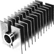 Plate or rectangular fins (Figure 6.31) are of low CS, resistance welded, and square or rectangular in shape. Fins are typically 3 mm thick and spaced 13 and 25.4 mm
|
TABLE 6.8 Helical Fin Tubes for Economizers
|
|
|
|
(b) |
|
FIGURE 6.31 Tubes with plate fins. |
|
Flue gas flow
|
|
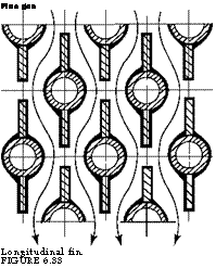
Flue gas Longitudinal fin. FIGURE 6.33 |
|
C |
![]()
|
FIGURE 6.32 Gas flow over fin tubes. |
 )
)
(1/2 and 1 in.) apart. Gas velocities are limited to 15 m/sfor clean gases. These fins are used in noncorrosive environments with gas, oil, and coal firing even with moderately high particulates. Rake-type SBs are required for keeping the surfaces clean. Coal applications present a danger of fly ash plugging.
3. Longitudinal fins (Figure 6.33) for coal application represent a popular method to economize on the surfaces. Staggered arrangement is usually adopted despite reports of fin-tube cracks developing over long periods of operation with oil-fired boilers. Plugging and erosion may be experienced in coal-fired boilers.
With every type of finned tube, HX care should be taken to direct all the gases only over the finned tubing and not over the bends to avoid gas bypassing as shown in Figure 6.32. Deflection baffles inside the casing are used for this purpose.
Staggered tubes yield a better heat-transfer rate and make the arrangement compact but at the risk of tube erosion due to dust in flue gases. Only for natural gas and light distillate oils and certain clean waste gases is the staggered arrangement suitable, whereas it is not so for coal and heavy oil applications. Heat recovery steam generators invariably employ staggered arrangement, as the GT exhaust gases are clean.
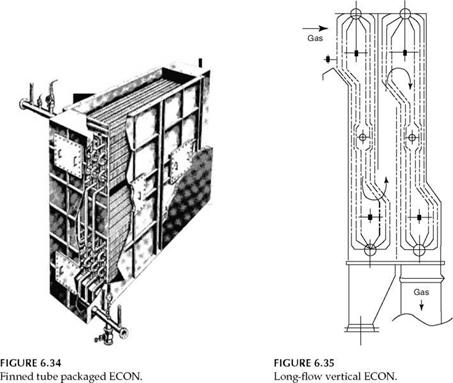
Most ECONs are horizontally disposed and fully drainable (Figure 6.34). Vertical tubes are employed in special cases such as BL recovery boilers and municipal waste fuel boilers in which sticky ash deposits readily on horizontal surfaces. The heat-transfer rates are lower and hence the surfaces required are correspondingly much higher (Figure 6.35).
Low CS is the material for both tube and fin for ECON construction except for ECONs in SC boilers. With a 450-480°C (—850 to 900°F) metal temperature limit, this material meets
|
|
The requirement even at the highest pressures in subcritical boilers. The tubes used range from 31.8 to 63.5 mm OD. For most applications, the tube thickness is 3.66 mm (9 swg) for horizontal ECONs.
Operating Concerns in Economizers
The main operational concerns of ECONs are
1. Gas-side tube erosion
2. Low external and internal temperature tube corrosion
These concerns are minimal with natural gas firing. Corrosion affects oil-fired boilers; coal is affected by both erosion and corrosion. A proactive design anticipating such problems and a careful O&M program can mitigate them.
Adherence to the maximum recommended gas velocities for a particular fuel can practically eliminate the erosion problems. In addition, understanding fuel behavior and previous experience with similar boilers are both essential to eliminate the constructional features that promote eddy formations in gas flows.
Low-Temperature External Corrosion
Economizer tube metal temperature is within a few degrees of the inside water temperature due to the high water-side heat transfer coefficient regardless of the gas temperature. The lowest temperature occurs at the point of water entry. Low water temperature results in the condensation of sulfur-bearing vapors on the tube surface, namely sulfurous and sulfuric acids, that may be at or below the acid dew point. This leads to the corrosion of tubes. The acid dew point depends on
1. Sulfur in the fuel
2. Percentage of H2O in flue gas
3. Excess air
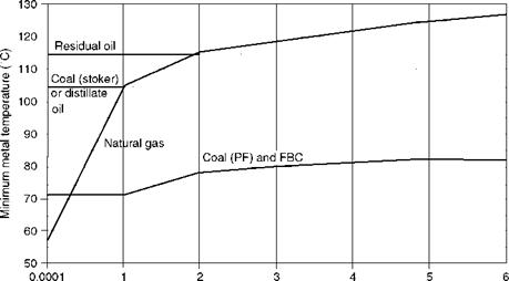
In addition, Fe, V, and other elements in the presence of O2 and H2O in flue gas act as catalysts to accelerate and increase the formation of the acid vapor, leading to higher acid dew point. Figure 6.36 gives the practical limits for the metal temperatures to avoid acid corrosion at low gas temperatures for bare tubes.
• These limits are applicable for both ECON and AH of CS execution.
• The limits for PF firing are lower than those for stokers because the fine PF ash adsorbs the acid and acts as an inhibitor.
• Field experience has shown that the rates of corrosion achieved by observing the limits shown in Figure 6.36 are within acceptable limits.
|
|
|
(1 ppm) |
|
% Sulfur by wt as fired |
|
FIGURE 6.36 Low-temperature corrosion limits (external) for CS economizer and airheater tubes for various fuels. |
|
TABLE 6.9 Minimum Metal Temperature Limit for CS Finned-Tube Economizers
|
|
Temperature (°F) |
• For extended-surface HXs, the permissible metal temperatures are higher because these HXs tend to foul faster and are more difficult to clean.
For extended-surface ECONs, the applicable limits are given in Table 6.9. For sulfur-free fuel, 65°C is the minimum temperature applicable. These limits are slightly higher for plain tubes for the above-mentioned reasons.
Low-Temperature Internal Corrosion
Internal corrosion of the steel tubes arises from:
1. Dissolved oxygen. This causes pitting, which is eliminated by deaeration of FW followed by oxygen scavenging.
2. Low hydroxyl ion (OH) concentration. This attacks steel faster and can be avoided by maintaining a pH value between 8 and 9. Sometimes the boiler water is circulated at the inlet to the ECON for maintenance of pH.
Strict adherence to the specified FW limits is one way to eliminate internal corrosion problems of ECONs. Please refer Chapter 4 for details.
Hot Air Temperature Limits in Firing Equipment for Various Fuels
|
Fuel |
Firing |
Hot Air a Must? |
Temperature Limit (°C) |
Temperature Limitation due to |
|
Gas |
Burners |
No |
450 |
Oxidation of air ducting |
|
Oil |
Burners |
No |
450 |
Oxidation of air ducting |
|
Coal |
Pulverized Fuel |
Yes |
400 |
Mill internals |
|
Coal |
Stoker |
No |
160 |
Coking of coal and clinkerization |
|
Coal |
Fluidized bed combustion |
No |
450 |
Oxidation of air ducting |
|
Bagasse |
Stoker |
Yes |
200 |
Stoker parts |
|
Airheater Classification |
![]()
|
Comparison of Tubular and Rotary Airheaters |
![]() Note: Hot air is always preferred to improve combustion but not strictly required and hence categorized "No." The air temperature limits are indicative and can vary depending on the combustion equipment.
Note: Hot air is always preferred to improve combustion but not strictly required and hence categorized "No." The air temperature limits are indicative and can vary depending on the combustion equipment.
|
Action |
Recuperative |
Regenerative |
|
Type |
Tubular airheater |
Rotary airheater |
|
1. Vertical tubes |
1. Rotating baskets (Ljungstrom) |
|
|
2. Horizontal tubes |
2. Rotating hood (Rothemuhle) |
|
TABLE 6.11 |
|
Parameter |
TAH |
RAH |
Remarks for RAH |
|
Type |
Static |
Rotating |
O&M issues in AH |
|
Construction |
Simple—fewer elements in AH |
More parts |
Very specialized |
|
Space |
More—tube withdrawal space required |
Compact |
|
|
Erection time |
More—more site assembly |
Less—more shop assembly |
|
|
Cold-end section COR-TEN |
Possible |
Possible |
|
|
Air leakage into gas space |
None |
Yes—increases as seals wear |
|
|
Increased forced draft, induced draft capacity? |
Not required: no leakage |
Required to make up for leakage |
More fan power |
|
On-load cleaning by SBs |
Mostly not needed—fouling is less in VTAH—possible in HTAH |
Required |
|
|
Fire hazard |
None |
Yes—particularly in oil fired boilers at low loads |
|
|
Repair of corroded HSs |
Easy—short tubes can be inserted in cold end |
Not possible |
|
|
Replacement of corroded |
Tube replacement more |
Easy—involves only |
|
|
Heating HSs |
Difficult |
Replacing baskets |
|
TABLE 6.12 |
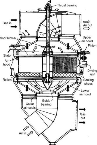
Heat in a moving rotor design. The heat exchange is, thus, through the medium of steel baskets subjected to hot and cold air streams alternately on a continuous basis. In the rotating hood design, the rotor remains stationary and the hoods for gas and air rotate to achieve the same results.
Both types of AHs are popular. The TAH is simple to fabricate and does not increase the existing auxiliary power or erosion problems (in case of coal-fired boilers), because there are no leakages from air to gas side such as in the case of an RAH and no maintenance issues because the assembly is static.
The RAH needs regular adjustment to the seals and is also maintenance prone but the real advantage lies in its compactness and simplified duct layout. With several shop — fabricated subassemblies, the site erection takes much less time. Also, with enameled baskets, lower gas-exit temperatures can affect boiler efficiency favorably.
Where space is not a constraint, erection costs are low presents and boilers are —400 tph or lower, TAH an economical proposition. When there is space constraint, RAH is the answer; it is a also preferred solution for utility boilers. A brief comparison is given in Table 6.12.
In the case of FBC boilers where there are high discharge pressures for forced draft (FD) and primary air (PA) fans, TAH is preferred to RAH because air leakage and hence maintenance of seals can be high, since air to gas differential pressure can be —2000 mm wg (—80 in.).
See (Figure 6.39).
• Heat transfer in a single bank in both vertical (VAH) and horizontal (HAH) systems is always in a perfect cross flow. Only when several banks are arranged does the AH become parallel or counter or mixed flow. The coefficient is adjusted depending on whether the set of banks are parallel or counterflow.
• With smaller tubes transporting air, the HAH enjoys a slightly better heat-transfer coefficient, making it more compact.
• Metal temperature is also a little higher in HAHs than in VAHs. But air pressure drop is marginally higher. Mostly the choice between the HAHs and VAHs is governed by the layout considerations of fans and ducting.
• For optimum design, AHs are designed with pressure drops not exceeding 65 and 40 mm wg for each bank for air and gas, respectively, for both VAHs and HAHs.
• The permissible mass velocities and typical heat-transfer coefficients are given in Table 6.13.
|
Tubular Airheater Air and Gas Mass Velocities and Typical Heat-Transfer Coefficients
|
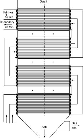
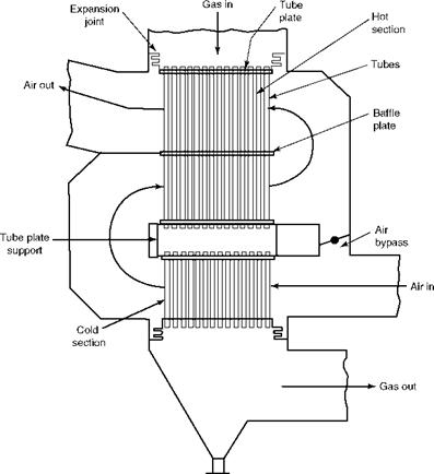
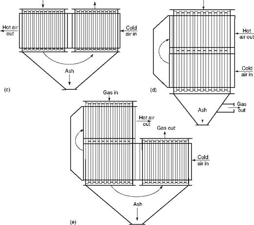
A VAH can be arranged in several ways and many banks. Figure 6.37 depicts a few arrangements of single — two- and three-pass AHs. With gas flowing inside the tubes, there can be two modes of airflow.
1. Gas through the tubes and outside air flow perpendicular to the tubes, as in Figure 6.37.
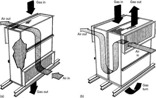
2. The airflow can also be arranged in longitudinal manner flowing along the tube axis on the outside, as in Figure 6.38.
Both HAH and VAH are depicted in Figure 6.39.
• The disposition of tubes in the HAH can be parallel or perpendicular to the drum axis. Sufficient free space should be available for tube withdrawal. Likewise, VAH head room below or space above should be equivalent to tube length.
• HAH is more amenable to be placed below the ECON, as ash tends to roll down over the horizontal tubes. In VAH, there is a fear of fouling and plugging of tubes at the cold end if ash in fuel is high.
• Soot blowers are generally not needed for VAH because it is a self-cleaning arrangement, unless phosphatic deposits are likely to occur at the cold end. A rake-type blower with steam nozzles individually directed toward each tube is the best answer.
Horizontal AHs are usually equipped with mass — or lane-type rotary blowers.
• Materials. As the gas temperatures rarely exceed 450°C and the metal temperatures are well within the CS limits, it is normal to use structural-quality low-CS tubes and plates in both types of AHs. Often in the cold-end AHs, tubes made of weathering steels, such as COR-TEN, are used for improved life.
• Expanded or welded? The tubes can be expanded in the tube holes or welded fully but lightly. Tube expansion is relatively easier and faster and hence more popular. Welding of tube to sheet is to be done with great care to prevent warping of the tube plate or damaging of the thin AH tube due to heat in welding.
• Thermal expansion. Provision for (1) expansion of tubes between cold and hot conditions and (2) relative expansion between tube and tube plates should be made properly.
|
|
|
Gas in Gas out Gas in
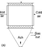
FIGURE 6.37 (a) Single-pass air and gas vertical tubular airheater in cross flow. (b) Three-pass gas and single-pass air vertical tubular airheater. (c) Two air and two gas vertical airheater. (d) One gas and two-pass air vertical tubular airheater. (e) Three gas and three air vertical tubular airheater in L-shape. |
|
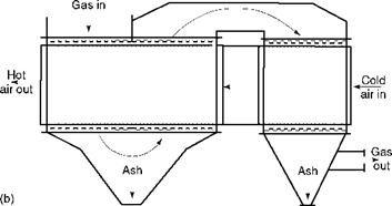
FIGURE 6.38 (a) Single-pass tubular airheater with air in long flow. (b) Two-pass tubular airheater with air in long flow. |
• Tube span/length. About 5 m maximum span may be considered for tubes in horizontal tubular airheaters (HTAHs) without intermediate support. Likewise, 5.5 m maximum vertical tubes can be considered for bottom supporting in a vertical tubular airheater (VTAH).
• Air and gas in VTAH. In a VTAH, it is normal to have gas and air move outward through the tubes in a staggered arrangement, although the reverse is also possible. The tubes are large—63.5 and 70 mm OD to prevent plugging at the cold end on account of fouling.
• Air and gas in HTAH. Air through the tubes and gas outside move in in-line arrangement for better cleaning. The tubes are smaller at 38.1 and 50.8 mm OD for better heat transfer without fear of tube plugging with clean airflow.
• Tube spacing in HTAH. In HTAHs, clear gap between tubes is 12.5 mm along gas flow. Across the gas flow, it is 25 mm for oil and gas and 38 mm for coal, for both stoker and PF systems.
• Tube thickness. Tube thicknesses are usually 2.0 or 2.3 mm (14 or 13 swg) for all fuels except for stoker firing on coal, where the gritty dust in flue gases demands extra sacrificial thickness; 2.3 or even 2.95 mm (11 swg) is used.
• Tube plates. There are two types—support and baffle plates. The former are load bearing and thicker at 25 or 30 mm and are suitably stiffened. The baffle plates are for locating and also for antivibration. They are made 16 or 20 mm thick (Figure 6.39b).
The features of both types of TAHs are summarized in Table 6.14.
|
TABLE 6.14 Construction Features of Vertical and Horizontal Tubular Airheaters
|
Finned Tubes for Tubular Airheater?
Usage of finned tubes has dramatically increased. Finned tubes are employed when the heat-transfer coefficients of two media are widely different. No other purpose is served by finning.
The constructional features of the HS of RAH are as follows:
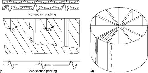
• The heat-transfer element of an RAH is the rotor filled with baskets containing packing of
• Corrugated sheets
• Undulated sheets
• Flat sheets
• The corrugated and undulated sheets separate the flat sheets, maintaining a distance, which
• Creates flow paths
• Increases HS
• Increases turbulence
• These sheets are 18-26 swg in thickness (0.46-1.22 mm) and spaced 5-10 mm apart. Close spacing and greater profiling produce higher turbulence and higher heat transfer and pressure drop. The fouling increases.
• Carbon steel for hot section and COR-TEN or enameled sheets for cold sections are the usual choice of materials.
• Thinner sheets and closer spacing for hot sections and thicker sheets and wider spacing for intermediate and cold sections are chosen to combat the erosion and fouling problems and also to contain the pressure drop. Thinner sheets vibrate in the flow and shed the dust but their lives can be short because they erod and corrode rather fast.
• The normal range of pressure drop is between 50 and 180 mm (2-7 in.) wg.
• Typically the HS packed in the baskets vary from 300 to 350 m2/m3 (90-105 ft2/ft3).
Moving rotor and moving hood designs are discussed briefly in Sections 6.6.4.1 and 6.6.4.2.
|
260 Boilers for Power and Process |
|
|
|
|
|
|
|
|
|
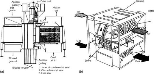
• In Figure 6.40a and b, the rotor filled with the heat-transfer packing material is enclosed in a stationary casing to which the inlet and outlet ducts of air and gas are connected.
• The rotor moves slowly between 1 and 3 rpm, driven by a drive motor assembly and is heated and cooled alternately.
• Seals on the top and bottom of the rotor prevent bypassing of air. Seals at selected places arrest the infiltration of tramp air into the AH.
• Mass-type SBs are installed on the gas inlet side for on-load cleaning of elements.
|
|
|
FIGURE 6.40 Moving RAH with (a) vertical shaft. (b) Horizontal shaft. (c) Corrugated packing. (d) Rotor sectors with corrugated packing. |
• As part of start-up and shutdown interlocks, the AH should be soot blown before and after service to keep it free from unburnt fuel.
• Both horizontal and vertical designs are used, with the latter more common in utility boilers. The horizontal design is popular with the package and field-erected boilers, firing oil and gas, as it fits very well where the gas exit and air entry are both at a low level.
• Figure 6.40a and b shows the typical bisector AH popular with oil and gas firing. The rotor is divided into two parts for the passage of air and gas. In a PF application, a trisector AH is required, as the pressure of PA is higher and temperature can also be higher. The rotor is then split into three parts. Even quadra sector AHs are used occasionally.
• Very large AHs can be built to this design. Rotors as large as 20 m diameter and weighing 800 t are in operation.
Rotating Hood or Rothemuhle Design
The stator, packed with corrugated material, remains stationary whereas the air hood rotates slowly picking up heat from the stator (Figure 6.41). All the variations available with moving rotor design are also offered in the moving hood designs. In both designs, air and gas bypass ducts with dampers are integrated with the AH. Safe operating temperatures of RAHs are nearly the same as those of TAHs.
The operating problems of AHs can be summarized as
1. Low-temperature corrosion
2. Fouling
3. Erosion
4. Fire
Low-Temperature Corrosion in Airheater
Airheaters are always provided with bypasses on both air and gas sides based on the process and layout. Air bypass is provided by allowing only a part of the air to pass through the AH to decrease cooling of flue gas. This is for raising the gas-exit temperature and along with it the cold-end metal temperature, which is usually a start-up precaution. A similar arrangement on the gas side is also possible. The bypass dampers are fully shut off during normal operation. Care should be taken to provide a minimum possible opening and a tight shutoff damper. The great tendency for leakage represents a permanent loss of efficiency.
Cold-end corrosion is a serious issue over which a constant vigil is necessary. The coldest point in the AH is where the cold air and exit gas come into contact. We assume that the metal temperature is the arithmetic mean of the two. With a wide difference in the ambient temperatures, there is always a danger of the cold-end slipping into the corrosion range with boilers designed for the lowest stack losses and causing serious
|
|
FIGURE 6.41
Rotating hood rotary airheater.
Consequences. By raising the air temperature, the metal temperature can be raised in two ways.
1. Hot-air recirculation from AH exit to FD fan inlet
2. Raising incoming air temperature by steam coil AH located in the cold-air duct
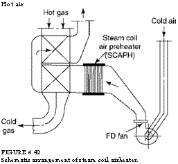
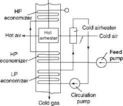
The former is relatively simple to install, does not add to the auxiliary power, but is not so efficient. Heating of air in a steam coil AH is expensive and power-consuming but a more reliable solution (Figure 6.42).
Either steam or FW can be used for heating air, depending on the layout. An LP ECON can also be used with the cold-end AH to raise metal temperature (Figure 6.43).
Fouling and Plugging of Airheater
Fouling is the deposition of gas-entrained ash. The deposition at low temperatures occurs due to the adherence of ash to the acid-moistened surfaces at the low end of the AH. Pressure
|
Hot gas
FIGURE 6.43 Low-pressure economizer for airheater temperature control. |
|
Hot air FIGURE 6.42 Schematic arrangement of steam coil airheater. |
 Drop increases as the deposits grow in size. If unchecked, gas passages become progressively choked or plugged. Regular soot blowing can reduce the fouling considerably. Offload water washing is carried out in many installations for deposit removal, as they are mostly water soluble. The reason for larger-diameter tubes in vertical TAHs, which cannot be easily soot blown, is to prevent the deposits from bridging and growing.
• Employing conservative gas velocities is a design-stage precaution against gas-side erosion, particularly for dusty fuels. Gas velocities have to be high to economize on the surfaces and evolve decent layouts and erosion has to be minimized.
• Normally erosion is at the entry to the bank where the velocities are the highest, and the maximum velocity limit should be applied at this point.
• For an HTAH it is normal to provide the top row with thicker tubes of, for example,
10 swg (3.25 mm) or erosion shields of typically 3 mm. Heat transfer in tubes covered with erosion shields suffers because there is no direct contact of the tube and gas.
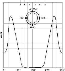
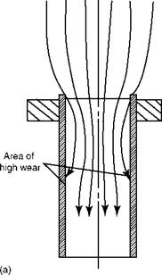
• Flow distribution baffles distribute the gas more uniformly across the inlet duct. Typical erosion of the tubes in a horizontal bank is depicted in Figure 6.44a and b. The maximum is 30-50° on either side of the tube axis.
• Areas near the seals in RAHs are subject to erosion due to higher velocity flow of ash through the narrow gaps. This can be controlled by using sacrificial material.
• In a VTAH, erosion occurs in the first 300 mm of the tube entry. Replaceable sleeves are used as protection.
Fires occur in RAHs mainly during startup and shutdown due to the agitation of accumulated ash heaps of unburnt carbon. They are particularly common with oil firing. It is important to follow the guidelines provided by National Fire Prevention Association
|
|
|
FIGURE 6.44 (a) Wear pattern in VTAH. (b) Wear pattern over horizontal tubes. |
|
Dusty gas Dusty gases |
![]() (NFPA) with regard to safe startup and shutdown procedures. Purging the furnace so that all accumulated unburnt gases are driven off is the most important step. Prevention of collection of ash and prompt removal of any debris are important to prevent fires. Soot blowing before startup and after shutdown can significantly reduce the fire hazard. Leakage of bearing oil is another source of fire in RAHs.
(NFPA) with regard to safe startup and shutdown procedures. Purging the furnace so that all accumulated unburnt gases are driven off is the most important step. Prevention of collection of ash and prompt removal of any debris are important to prevent fires. Soot blowing before startup and after shutdown can significantly reduce the fire hazard. Leakage of bearing oil is another source of fire in RAHs.
Further Readings
Brasseur, O. and Daschmann, G. The recuperative plate heat exchanger as the new concept to heat air in fossil power stations with a view to improve efficiency. Balcke-Durr GmbH, Ratingen, Germany.
Designers’ Guide: Zurn Two-Drum Steam Generating Systems, a company publication.
Reason, J. (Ed.), 1984, Flue gas heat recuperators: which is the best? Power, October.
Singer, J. G. (Ed.), 1991, Combustion Fossil Power, 4th edition. Combustion Engineering, Inc., Windsor, CT.
Smittie, D., 1980, Maximise heat recovery from hot flue gas with finned tubing. Tranter Inc., Kentube Division, Power, August.
Steam its Generation and Use: Various editions.


 27 августа, 2013
  admin
admin 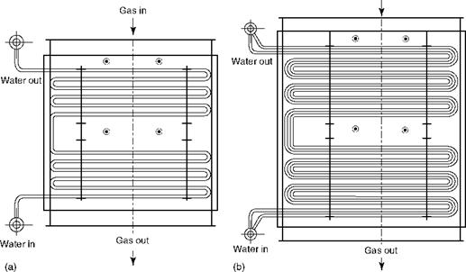

 Опубликовано в рубрике