Fabricated parts of the boiler can be divided broadly into the following categories:
1. Unheated pressure parts (PPs) (coded parts kept mostly outside the gas pass)
2. Draft plant items (mainly sheet metal work)
3. Structures (mainly rolled and fabricated steel work)
These parts do not participate in heat transfer, other than in the gas-swept portions of the drums in the bidrum bank. Nor are they finished auxiliary items that contribute to the performance of the boiler. The fabricated items are mostly static and perform the following background functions:
• Support the boiler, its various components, and machinery
• Transport the fluids, gas, and air (in flues and ducts), and water or steam (integral piping)
Steam drum. In natural circulation boilers, the steam drum occupies a position of importance because of:
• It is the heaviest PP and often the heaviest component.
• The layout and erection of the boiler revolve around it.
• It takes the maximum time for manufacturing and needs the costliest machinery.
• Moving it demands a high level of logistics.
• It needs the heaviest crane or lifting tackle during both fabrication and erection.
Thermodynamically, however, a steam drum is merely a surge tank in the circulation system to which the following parts are connected:
• Economizer (ECON) outlet and SH inlet pipes on one side
• Downcomers and risers on the other side
Under steady operating conditions when the flows are balanced, the steam drum produces a steady water level. Drum water level is one of the most important parameters, of a boiler control system. The other important function of the steam drum is to house the drum internals (see Section 7.2.1.3), which perform the following functions:
1. Saturated water from evaporator circuits, which contain varying amounts of steam, is separated by the steam seperators. Water-free steam to the SH and steam-free water to the downcomers are required of steam seperators and purifiers.
2. Chemical dosing to maintain the chemistry of the circulating water.
3. Continuous blowdown (CBD) of drum water to keep the carryover under specified limits.
Water drums are present only in the bidrum boilers and play a less important role.
• A water drum acts like a large header connecting the riser and downcomer tubes of the bank.
• It feeds the downcomers to the various evaporator sections.
• It is where the sludge is withdrawn for disposal in many boilers.
Sizing of Steam and Water Drum
Steam-drum sizing. The size of the steam drum should be adequate to meet the following requirements:
Boilers, the water in the large-bore downcomers add to the water in the steam drum, thus providing the total water-holding.
3. Sufficient swell volume is important for vertical waste heat recovery boilers (WHRBs) or heat recovery steam generators (HRSGs) with evaporator tubes in coil construction. As all the tubes are joined to form a coil (and not left as individual tubes as in a bidrum arrangement) during the startup or a large load change, there is a sudden rush of all the accumulated steam and water in all the legs, causing a massive increase of the drum water. If the drum diameter is too small, the water will overflow into the SH tubes. The amount of swell depends on the boiler construction and the process variations. The start-up conditions of a gas turbine (GT) are very severe on HRSGs, as the GTs attain full-load conditions in minutes. In vertical WHRBs and HRSGs, where gas flow is vertical and evaporators in horizontal coils, the steam drums are larger and governed by the swell conditions.
Drum diameters for the same function reduce with increasing pressure, as the specific volume of steam progressively reduces at higher pressure. Steam drums, normally specified by ID, range from —1000 to 2200 mm (—40 to 87 in.) in conventional boilers and even 2800 mm (110 in.) in HRSGs. The smallest steam drums are usually in package boilers starting at 914 mm (36 in.). Popular sizes are 1067 mm (42 in.), 1220 mm (48 in.), 1370 mm (54 in.), 1524 mm (60 in.), and occasionally 1676 mm (66 in.) for low-pressure boilers. Larger sizes of 1676 mm (66 in.) and 1830 mm (72 in.) and above are mostly found in utilities or WHRBs/HRSGs. Steam drum thicknesses vary from as low as 25 mm to as high as 250 mm (—1 to 10 in.).
Water-drum sizing. Water drums were known as mud drums because of a large amount of sludge or obsolete designs. The water drum is always smaller than the steam drum as there are no important internals and, more importantly, the number of tubes to be expanded is usually limited to the bank tubes, usually
• 10 or 11 in oil/gas package boilers
• 16-20 in two-pass boiler banks (BBs)
• 18-22 in single-pass BBs
In package boilers, which are shop-assembled, the bottom drums are sometimes made from rolled seamless pipes of 610 mm (24 in.) OD using special ultracompact expanding tools. The minimum diameter is 760 mm id (30 in.). The other popular size is 914 mm (36 in.) and occasionally 1067 mm (42 in.). Table 7.1 gives the popular sizes of the steam and the water drums for all types of boilers.
• These sizes are indicative, and the manufacturers use different sizes.
• The drums are made as per the availability of the dies for making the dish ends.
• Drums larger than 2210 mm (87 in.) can also be made mainly for large HRSGs.
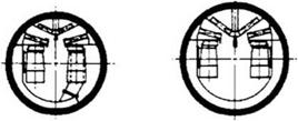
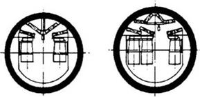
• Usually from 1370, 1830, and 2210 mm id (54, 72, and 87 in.), steam drums have the capability to accommodate two, three, and four sets of cyclones (Figure 7.1).
Expanded and stubbed drums. In all the bidrums the bank tubes are expanded in the boiler drums, and these drums are called expanded drums. The tube holes are generally —1 to 2 mm larger than the tube OD. After considering the tolerance of the tube OD, a small clearance (between the tube and the hole) has to be added to arrive at the hole ID.
|
TABLE 7.1 Range of Popular Steam and Water Drums
Steam drum (MWe) ID = inner diameter. |
|
|
|
1370 mm (54 in.) 1524 mm (60 in.) |
|
1676 mm (66 in.) 1830 mm (72 in.) |
FIGURE 7.1
Typical drum sizes and rows of steam separators.
Oversized holes require a lot of tube expansion with resultant excess cold working, whereas undersized holes create problems of tube insertion and inadequate expansion.
The resulting ligament efficiency (p — d)/p, where p is the pitch and d is the bore of the hole, for steam drum is generally approximately
• 38-42% for oil/gas package boilers with 10 or 11 bank tubes
• 48-51°% for other bidrum boilers with 18-22 tubes
For higher pressures the drums tend to be thicker due to the reduced allowable stresses. Usually the ligament efficiency due to convection bank tubes is made lower than that of roof tubes and risers and hence it governs the drum thickness.
In radiant boilers, with the absence of BB, only the downcomer and the riser stubs are required to be welded and hence the term stubbed drum. Fewer risers and downcomers are required in comparison to the bank tubes. Adequate space in the drums for welding the stubs produces ligament efficiency of —80-85%. The steam drum naturally is much thinner.
The bottom drum is usually chosen with up to 2% lower ligament to take advantage of its smaller diameter.
The steam purifier generally is a combination of steam separators and steam dryers. Also see Section 4.5.1. Steam purification is usually a two-stage process consisting of
1. Steam separation in which steam is separated from water due to the density difference
2. Steam drying in which last traces of moisture are removed by adsorption
Steam separation is achieved at high velocities by
• Deflection baffles or baffle-type separators
• Cyclone or centrifugal separators
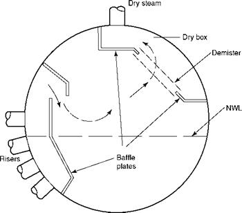
Deflection baffles or baffle-type separators (Figure 7.2) are inertial separators that utilize the change of direction to separate steam and water, which are used up to —150 bar drum
|
FIGURE 7.2 Deflection baffles or baffle-type separator. |
Pressure. They create less pressure drop. They are available in a variety of proprietary configurations:
• They are much simpler than cyclones.
• They are less expensive.
• They require much less time to dismantle and install, making site inspection easy.
• They hasten the drum-making process as they need not be installed inside the drum before delivery for trial assembly.
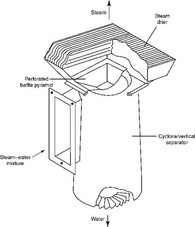
Cyclone or vertical separators (Figure 7.3), in contrast, work on the principle of centrifugal separation and are used for all pressures because the action is more positive. The steam- water mixture enters the cyclone tangentially at —6-8 m/s. The density difference throws the water particles to the periphery and keeps the steam at the center. The steam travels upward, passing through a perforated baffle pyramid, where it is decelerated and spread across the whole area of the steam drier, which provides additional fine separation. Water
|
FIGURE 7.3 Cyclone or centrifugal separator. |
Travels downward in a vigorous swirl. The action is so dynamic that the drum water is kept out of the cyclones, although they are immersed up to half of their height. The cyclones
• Provide a more positive steam separation
• Consume more pressure drop
• Are used for all drum pressures up to 210 bar
• Are more expensive and take more installation time
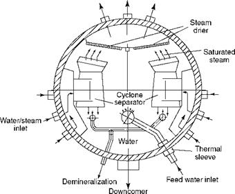
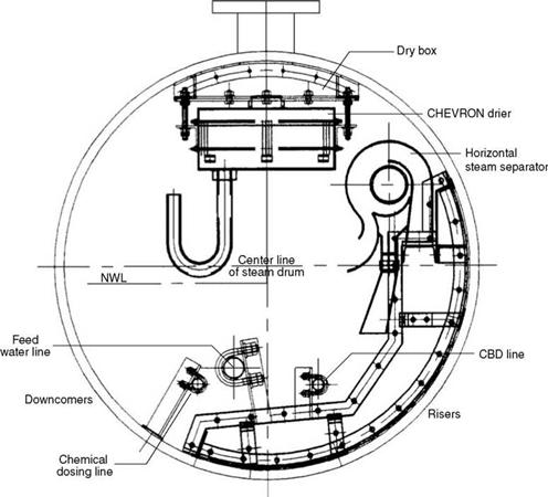
The two types of cyclone/centrifugal separators are vertical and horizontal (Figures 7.4 and 7.5). Both are proprietary designs developed by different firms. The horizontal cyclone arrangement takes slightly less space for the same duty. But in terms of performance, there does not seem to be much difference. Figures 7.4 and 7.5 represent stubbed and expanded drums, respectively.
Steam drying. Drying devices produce dry steam. There are two methods, and both reduce steam-water velocity so that the water gets attached either to the plates or to the wires of the driers. The two types are:
1. Corrugated plate assemblies (also called as chevrons)
2. Demisters
In corrugated or sinusoidal plates, as the steam containing traces of water passes through the pack of corrugated plates, water adheres to steel by its natural affinity by adsorption. The formed water film slides down into the water space by the inclination of plates. It is normal to make the plates with stainless steel (ss) material as ss alone provides a highly polished surface that helps the water to roll off easily. Besides, ss is corrosion-resistant.
|
Saturated steam outlet
FIGURE 7.4 Drum internals with two sets of vertical cyclones in a stubbed drum. |
|
Dry steam
FIGURE 7.5 Drum internals with single set of horizontal cyclones in an expanded drum. (From Foster Wheeler Corporation. With permission.) |
In the demisters, traces of water are intercepted by the ss mesh, which is like steel wool. The diameter of the wire and the density of the packing are carefully selected for effective trapping of water.
The most important factor to ensure dry steam is to secure uniform loading of the steam separators with steam-water mixture under all loads. The manner of connecting saturated steam pipes at the top of the drum plays a very important role in the distribution of the steam-water mixture. Connecting the SH tubes directly to the drum is perhaps the best way. Providing several equally spaced saturated steam pipes from the drum to the SH inlet header is another good practice. In small boilers, sometimes a single pipe is used for evacuating steam, but it is not good for steam purification.
The type of steam purification equipment is dependent on the steam generation per unit length of the drum. The steam generation is quite low in stoker-fired boilers as they use the slow-burning fuels. Generation is high in oil — and gas-fired industrial boilers. Pulverized fuel (PF) boilers for utilities generate the most steam. Package boilers for oil and gas have very long drums as the firing is along the drum axis, and steam per meter length appears
|
TABLE 7.2 Typical Steam Output in Te/m Length of Drum
|
Low, although the rating of all areas of the boiler is high. Considering that downcomers occupy 35% length of the drum, it is more appropriate to increase the steam loading by —1.5 times, that is, 3-15 Te/m. Table 7.2 compares the steam loadings for various types of boilers and fuels.
Drum internals include steam separation and purification equipment and other secondary equipment such as the following:
• Feed water (FW) distribution piping
• Chemical-dosing piping
• Blowdown piping
Figure 7.4 shows the arrangement of all the drum internals having vertical cyclone separators in a single-drum boiler with large bore downcomers.
Steam separation. Two rows of cyclones are shown in Figure 7.4. Depending on the steam release per meter length of the drum, the cyclones can be arranged in one, two, or three rows.
• The design of the drum internals has to meet the fundamental requirement that they are installed in the drum only after the boil out is complete and the magnetite (Fe3O4) layer on the inside of the drum is fully formed.
• All drum internals must be of bolted construction, including the baffle plate, so that they can be installed and reinstalled easily. The drum inside the surface must be inspected at regular intervals in an operating boiler.
• The drum internals have to be compact enough to permit their assembly inside the drum manually and allow them to be dismantled and reinstalled quickly.
• The baffle plates separating the steam and the water spaces and made of several small components, have to be of good fit and finish to create a tight compartment that prevents steam from escaping into the water space.
• Great care is needed in the assembly of drum internals. The danger of the small fasteners and fittings falling inside the drum and escaping into various pipes, can cause flow obstruction, leading to serious damage during operation due to overheating.
• Depending on the arrangement, the FW may enter the steam drum at one or several locations connected to a single pipe with several perforated holes to permit a uniform distribution and a steady entry into the water space of the drum.
• Blowdown water, to limit and maintain the concentration of solids in the drum water, is collected at the bottoms of the cyclones by means of perforated pipes.
• The small chemical-dosing pipes run the entire length of the steam drum to distribute the chemicals.
• All drum internals are nonpressure parts (NPPs) because the same drum pressure acts inside and outside.
• All nozzles carrying cold liquids should have thermal sleeves to prevent thermal shock to the drum (Figure 7.4).
The steam drum is located outside the flue-gas path in single-drum boilers and inside the gas path in the bidrum boilers. The metal temperature can be considered the same as the saturation temperature of water in unheated drums, whereas it is a few degrees (<10°C) higher in heated drums. The drum thickness is governed by the following elements:
• Ligament efficiency
• Inside diameter
• Design pressure
• Material of construction
Drum thickness is the governing factor in limiting the startup and shutdown rates of a boiler, particularly as the drums attain thicknesses —100 mm and more.
In thicker drums, the difference between the inside and the outside temperatures of the drum shell on an accelerated loading or shutdown can create differential stresses, leading to over-stressing and failure. This can be avoided by adopting lower ramp-up rates for the boiler loading.
• For drums with expanded tubes, the criterion is the loosening of tubes during accelerated cooling, because the thin tubes contract faster than the drum shell.
• Typically the heating is limited to 1°C/min of the saturation temperature for expanded drums, to prevent the reverse of the above condition.
• For fully welded drums, based on the stress analysis, limit the temperature differentials for a certain pressure
-Across the drum plate
-Between the top and the bottom of the drum
These limits are different for heating and cooling. Naturally for higher rates of starting and cooling, boilers with no expanded tubes, stubbed drums, are better.
Downcomers, Supplies, and Risers
Supplies and risers are pipes that feed and evacuate water walls and other evaporator surfaces, respectively.
• Downcomers are the supply pipes that start from the drum to feed the water walls and convection banks.
• Because saturated water flows through these downcomer pipes, they are at the same temperature with no relative expansions among themselves or the EVAP banks they are connected to.
• They made of CS unless at high pressures; low-alloy steel such as SA 213 T1 (0.5% Mo) or T11 (or 1.25% Cr and 0.5% Mo) is used for thickness reduction.
The large-bore downcomers take water from drums for further feeding.
• They usually vary from 193 mm (7 3/4 in.) to 457 mm (18 in.) OD.
• They fit the layouts of tall boilers very well but not the oil — and gas-fired package boilers.
• Large-bore downcomers are almost indispensable for radiant boilers where they are used for bringing the saturated water to lower headers.
• In tall bidrums they are connected from the bottom drum.
• Many times these pipes are not directly welded to the drum but hung separately and connected with small pipes for better layout considerations. Also, they avoid heavy welding on the thick-walled drums, which is better for the life of the drum.
• When large-bore downcomers are directly attached to the drums, antivortex baffles have to be installed at the entry so that the vortex effect is broken, and the steam bubbles are not sucked into the downcomer circuits. This can weaken the circulation by reducing the saturated head. These baffles are only a pair of flats inserted into the entry of the downcomer at right angles, which break the vortices. Supply pipes start from the drum in small boilers and from the downcomers in large boilers.
• Circulation calculations can prove the adequacy of the number and the size of the supplies provided.
• New supply pipe arrangements should be checked for circulation adequacy.
• At low and medium pressures, supply pipe areas are generally 1/4 to 1/6 times the area of the evaporator circuit they serve, depending on the pressure.
• At higher pressures, as the circulation ratio is lower, the area required for supplies is greater.
Riser pipes connect the top headers of the water walls to the drum in the area below the
Separating baffle for evacuating the steam and water mixture.
• The specific volume of the steam-water mixture is greater than the saturated water. It is essential that the area of risers be larger than the area of supplies for any circuit.
• For low and medium pressures, area for risers is generally 1/3 to 1/2 times the area of water wall and even higher for the division walls.
• The area here is also higher for higher pressures.
• For all sizes of boilers, arranging riser pipes, clearing the suspension hangers
From the roof, and leading them to the drum at some uniform spacing, are timeconsuming and difficult processes.
• Riser pipes connecting the farthest header to the drum are generally susceptible to sagging and mild vibration when they are longer than 6 m. Often they are supported at some midpoint.
As the boiler sizes and pressures increase, the ratio of risers, downcomers, and supplies in the total PPs also increases disproportionately.
Integral piping is located on the boiler island, that is, between the feed-check valve and the main steam stop valve (MSSV). The term covers all pressure piping comprising
• Soot blower
• Blowdown—continuous and intermittent
• Drain and vent—sampling
• Terminal piping—feed inlet, main steam outlet, and RH inlet and outlet pipings
Most integral piping, except for terminal piping and SB main piping measures <76 mm NB and many times it is site-fabricated and erected.
This piping forms the bulk of the integral piping. Starting usually from the SH intermediate header or the drum, the piping is routed up to the individual SB.
• A main isolating valve, a pressure-reducing valve, and a safety valve are located on the main SB line before it branches to an individual SB.
• The main line terminates at some convenient lower level with a draining arrangement complete with a steam-trap assembly.
• Each branch terminates at its respective isolating valve upstream of the blower.
• Appropriate slopes for the main and the branch lines provide proper draining of the whole piping, which is essential to ensure that no water particles are deposited in the soot-blowing steam. Impingement of water particles at high velocity can rupture the tubes inside the boiler as the dust laden steam jets are very erosive.
• Piping to retractable SBs is often stress-analyzed for flexibility.
• Soot blower main piping is usually of CS. If connected to SH headers, it can be of low-alloy steel of the same mix as the headers to which it is connected.
More details are given in Chapter 8.
As explained in Chapter 4, boiler water is dosed with chemicals and conditioned so that it does not
• Attack the wet parts and cause corrosion
• Leave behind scaly deposits, which cause tube overheating and corrosion.
• Contribute to carryover
|
TABLE 7.3 Types of Blowdown
|
As the steam is evaporated, a concentration of reacted chemicals and solids is left behind by the steam, which has to be removed for maintaining the specified limits. While operating the boiler, this is done by blowing down. There are two types of blowdowns as given in Table 7.3.
• Blowdown piping extends from drums or downcomers to the blowdown tanks.
• Intermittent blowdown is dirty as it contains sludge from the boiler, and the IBD tanks are vented to atmosphere with no flash steam recovery.
• Continuous blowdown is clean and continuous and hence amenable to flash steam recovery on large units or with common CBD tank for multiple boilers.
Drains
Boiler drains are located at the bottoms of the saturated circuits and SH and RH circuits. The drains have several purposes.
• Draining of the boiler water from the water walls and downcomers for inspection and emptying.
• Lowering the water level in the boiler from the downcomers or the bottom drum in an emergency during operation.
• Draining of steam from the SH headers during start-up to induce flow through the SH coils for keeping the tubes cool and to help raise the steam temperature faster.
The following constructional aspects are worth noting.
• All the lower headers have drain connections. The upper headers do not need them as they are drained into the lower headers by connecting tubes.
• Headers longer than about 4 m are provided with drains on either end.
• Water-wall drains are all connected to a ring main, which is then connected to the IBD tank.
• During normal operation of the boiler, the water walls are not to be drained. Draining would disrupt the circulation and cause serious damage to the tubes.
• Superheater drains are usually designed to —12.5% steam flow and are connected to the CBD tank.
• All pipes to the drain valve are designed for full boiler design pressure and half pressure from the blowdown valve to the blowdown tanks.
Vents
• Boiler vents are always at the top headers and the steam drum for the removal of air.
• Air-vent sizes are small, <50.8 mm NB.
• A start-up vent on the final SH header must vent substantial amounts of steam, typically —30%, to induce a good flow through the SH to get steam temperature high enough to avoid temperature mismatch with turbines during start-up. Startup vents usually vary in size from 100 to 200 mm. All start-up vents need silencers. Piping to the vent valves is designed for full boiler pressure.
All drain and vent piping can be of CS except for SH vents and drains, which are of low — alloy steel of the same composition as the headers from where they start.
Sample coolers are usually placed on the firing floor or near the control room. Sample pipes bring steam and water samples from the respective tapping points to the coolers. It is normal to provide at least four sampling points in a boiler for
1. Superheater steam
2. Saturated steam
3. Feed water
4. Drum water
A pipe size of 25 NB is commonly used. Sampling piping is required to be ss as corrosion products, which may easily form with CS, cannot be permitted in water or condensate samples and will lead to results.
Some boiler contracts are based on the battery-limit concept in which all the equipment and piping within the battery are to be supplied by the boilermaker. All the piping, both incoming and outgoing, must be taken up to the battery limits. This concept is very popular in the hydrocarbon industry. The terminal piping up to the limits of the boiler island is usually designed for flexibility.
Permissible Fluid Velocities in Piping
Table 7.4 provides a range of velocities for sizing of boiler integral and external piping. The lower end of the range is chosen to keep pressure losses low. The higher end is chosen for short runs of piping and shortages of available economical pipe size. At the proposal stages, it is prudent to adopt midrange velocities.
|
TABLE 7.4 Permissible Range of Fluid Velocities in Pipes
|
Flues, Ducts, Hoppers, and Casing
Flues and ducts are rectangular or round ducts meant to convey flue gas or air,
Respectively.
• Flues carry flue gases whereas ducts carry air.
• Flues are generally made of 6 mm and ducts of 5 mm thickness. In small-package boilers, with short lengths, 4 mm is also used for both flues and ducts.
The following points are worth noting about flues and ducts:
1. Depending on the internal pressure, suitable external stiffening must be done to prevent distortion and vibration due to the movement of the high-velocity air or gas.
2. For large ducts of 2 m or more, internal bracing is required. Structural members or pipes are welded firmly to the opposite sides to maintain the shape.
3. When equipment is interconnected, the duct sizing is governed by the flange dimensions at two ends and not by velocities.
4. For straight distances, classical velocity limits are applied and pressure drops are checked to determine optimum sizing.
5. Circular ducts are the most economical. Higher velocities can be employed for the same pressure drop and hence the areas are smaller. Also, less stiffening is required as the circular shape is inherently more rigid. Less steel is required.
Typical permissible air and gas velocities are given in Table 7.5.
|
TABLE 7.5 Permissible Air and Gas Velocities in Flues and Ducts
|
Hoppers
Hoppers are used for collecting ash at the bottom of a bank and also for facilitating flue — gas turns.
• They are usually of 6 mm thickness.
• The slopes of their sides should result in valley angles at the corners that should be greater than the angle of repose of ash. In coal-fired boilers, the slopes should be 70° or more to the horizontal. This will yield valley angles at the corners >63°.
• High-temperature hoppers, such as those below the BB, need to be covered with refractory tiles or insulating blocks to prevent overheating. Choice of tile or block depends on whether the ash in flue gas is abrasive or not, respectively.
• Low-temperature hoppers, such as those below the ESP, have to be equipped with fluidizing nozzles for aiding a smooth ash flow. Also, heating pads have to be provided to prevent ash from cooling down and absorbing moisture and turning to lumps when unit is shut down. Ash is very hygroscopic.
Dampers in the paths of air and flue gas work on flow streams in the following four ways:
1. Isolation
2. Control
3. Diversion
4. Nonreturn
All boiler dampers are fabricated from sheet steel to the required sizes and specifications. There are four types of dampers.
1. Louver or flap-type dampers for control and isolation duties. However, they cannot provide a tight shutoff.
2. Guillotine dampers for isolation duty. Even 100% shutoff is achievable.
3. Diverter dampers for diverting the flow as in HRSG bypass.
4. Nonreturn flap dampers for preventing flow in reverse direction, such as a weather damper in the HRSG stack.
Louver or Multiflap Dampers
Louver or multiflap dampers (Figure 7.6) are the most common because they are light, occupy less space, can be inserted in any position, and are mechanically simple. But they offer a little more pressure drop, are not leak tight in closed position, and are more prone to leakages through the shaft seals.
Large hot dampers, which are operated infrequently, become jammed and the functioning is often indifferent unless the damper construction is sturdy, and the actuator is adequately powered.
|
R 1 II |
-1 It — F“ |
Fl“ |
« |
|||
|
J——————— |
||||||
|
Ll II 1. ,J |
V I 1 |
L |
||||
|
I |
||||||
|
111 II II |
IH |
— |
||||
|
III 4 |
« I L_______ 1………. |
|||||
|
Li |
— |
|||||
|
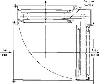
FIGURE 7.6 Three-flap louver damper with power cylinder actuator in closed position. |
|
|
FIGURE 7.7
Leak tightness.
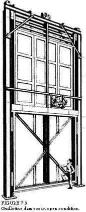
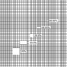
The guillotine dampers are less flexible, heavier, and erode their seals. But they offer less pressure drop and provide a good shutoff. In areas of lethal gases, guillotine dampers can provide gas tightness with shutoff levels exceeding 99.9%. This is achieved by sealing system-employing air to inflate the seals on either side of the sealing plate. The difference between 99 and 99.99% sealing is large as shown in Figure 7.7. A typical guillotone damper is shown in Figure 7.8.
The diverter damper (Figure 7.9), used between the exhaust of GT and the inlet of HRSG should be capable of withstanding temperatures between 50 and 650°C and pressures
|
Gas diverted
FIGURE 7.9 Diverter damper in boiler running condition. |
|
FIGURE 7.8 Guillotine damper in open condition. |
 Up to 400 mm w. g. A diverter damper should, during normal operation, provide very tight shutoff. Any leakage of gases causes loss of cycle efficiency. Dampers are large, usually constructed of stainless steel, to withstand high pressures and temperatures from turbine gases.
Weather dampers are required in vertical HRSGs to prevent the wetting of tubes due to rainfall. In a vertical HRSG, the stack is mounted on top of the unit. The stack diameters are large and rain water is bound to enter a banked HRSG unless the stack is closed. During operation, the flow of pressurized gases at —16 m/s keeps the rain water away and also the flaps open. The weather damper is a circular device fitted at the bottom of the stack and has a pair of eccentrically supported semicircular halves that are kept open by the force of gases during running and are closed when the upward force is absent when the unit is down. Motorized actuation helps the gases in initial lifting of the weather damper.
Expansion joints are introduced in the ducting for
1. Vibration isolation
2. Absorption of differential thermal expansion
An expansion joint for vibration isolation is often called a v-breather, and consists only of a single loop. All the fans invariably have v-breathers at their connections to the ducting. The expansion joints are of two types: (1) metallic and (2) fabric. The metallic joints have been in use for a long time.
• They are more rugged and have a longer life.
• For very erosive coals, metallic joints are preferred as they can withstand erosive forces better.
Fabric joints are of more recent origin.
• They are far more flexible.
• They facilitate construction as alignment need not be so accurate.
• They can accomodate expansion.
• They can accommodate distortion.
From life and erosion aspects, metallic joints appear to be favored for coal and allied applications. Improved fabrics and lower costs are fast increasing the acceptance of fabric joints, as the flexibility is far better.
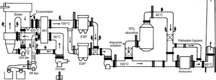
Figure 7.10 presents the locations and temperatures of various types of dampers and expansion joints in a typical PF-fired boiler.
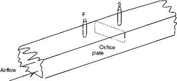
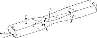
Airflow measurement by special devices is necessary in conventional boilers. In certain boilers, pressure drop across SH, BB, or airheater (AH) can also be used to measure airflow, if there is no deposit formation and the calibration remains unaffected. In all the other cases, airflow is measured by one of the following three methods (Figures 7.11 through 7.13).
1. Orifice plate
2. Venturimeter
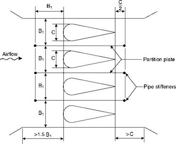
3. Aerofoil
The following considerations dictate the choice of the device:
1. Layout of the boiler plant
2. Upstream and downstream straight lengths of duct available
3. Permanent pressure drop across the device
4. Cost
Table 7.6 compares the measuring devices.
|
|
|
Mills |
|
Guillotine damper |
|
OP Louvre damper |
|
IQ fan Absorber bypass |
|
Expansion joints |
|
FIGURE 7.10 Dampers and expansion joints in a typical pulverized fuel boiler. |
|
Fabricated Parts |
![]() M
M
Oo
|
|
FIGURE 7.11
Orifice plate.
|
|
FIGURE 7.12
Two-sided venturimeter.
|
|
FIGURE 7.13
Multiaerofoil.
|
TABLE 7.6 Comparison of Airflow Measuring Devices |
|||||
|
Device |
Location |
Measuring Difference (mm w. g.) |
Permanent Loss (mm w. g.) |
Relative First Cost |
Remarks |
|
Orifice |
Air duct |
75 |
40 |
1.1 |
For small boilers in which power loss is not important and is used frequently in tempering air duct |
|
Venturimeter |
Air duct |
75 |
22 |
1.4 |
Lower cost and loss but requires longer duct length than aerofoil |
|
Aerofoil |
Air duct |
75 |
18 |
2.1 |
Requires shorter duct than venturi and multiple aerofoils reduce length |
|
Convection Bank |
Gas pass |
75 |
0 |
0 |
Only for clean fuels and banks in crossflow and not for longitudinal flow |
For reliable readings, there should be 10 upstream and 5 downstream equivalent diameters of straight lengths of ducting available, so that adequate flow straightening takes place. When there is a shortfall due to layout constraints, flow straightness should be inserted in the ducts.


 28 августа, 2013
  admin
admin 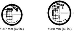
 Опубликовано в рубрике