Until early 1970s, the HRSGs were merely simple HXs placed behind GTs for heat extraction. As the GTs became bigger, the oil or gas package boilers were modified for the GT exhaust. As the GTs grew enormously in size and complexity, the HRSGs also kept pace. They assumed a distinct form of their own. Today, they are made in vertical and horizontal designs.
The exhaust gas temperatures range from 415°C (780°F) to 630°C (1166°F) and flows up to —2660 tph (—740 kg/s or 1630 1bs/s) in power plants from which the HRSGs have to extract steam.
Conventional Boilers versus HRSGs
In most ways, HRSGs are different from other boilers.
• Unlike a coal-based power plant, which is built around the boiler, the gas-based power plant is planned around the GT and ST, with HRSG in a secondary position of importance.
• An HRSG is nowhere near the size and complexity of a utility coal-fired boiler, although it has importance in the CC because:
— The delivery of the HRSG is the most critical aspect in a gas-based power plant.
— The overall efficiency of the cycle is governed by the efficiency of the HRSG.
— The price of an HRSG may exceed the price of the ST.
|
To the Stack Cold
Gas |
FIGURE 14.15
Preheater in heat recovery steam generator.
• Even in the largest CC power plants (CCPPs), the size of the HRSG is only as big as a large industrial boiler.
• With multiple pressure and temperature levels, no fans, no firing in many cases, no refractory, no ash concerns, and completely finned tubes, HRSGs are different in concept and construction.
• A main HRSG is light on control instrumentation. Multiple pressure levels with multiple drums require one to three sets of water-level controls. Likewise, there may be multiple attemperator controls. There are no draft, combustion, and load controls.
• In the GT cycle, the LP heater is avoided and replaced by the preheater section of the HRSG. Condensate from the condenser at —30 to 40°C is admitted into the preheater section of the HRSG for direct heating by the gases. To prevent the corrosion of preheater tubes, hot condensate from preheater exit is recycled by pumps to a temperature of 65-85°C, depending on the sulfur content of the gases. This way the exit-gas temperatures from the HRSG can be lowered dramatically compared to the conventional boilers (Figure 14.15). Carbon steel (CS) tubes are employed for preheaters unless stainless steel (ss) is warranted due to indifferent water conditioning. A deaerator is also integrated into the HRSG as an LP feed water heater (FWH) followed by the LP evaporator (EVAP). The HP FWH is turned into an HP economizer (ECON).
• Attemperation in a conventional sense is not applicable for the HRSGs as they are downstream of the GTs and merely extract heat as it comes. There is no control or turndown. This is further elaborated in Section 14.4.7.
Heat recovery steam generators are integral parts of CC and cogen plants, working at the back-end of the GT and responding to the GT dynamics. A broad understanding of the GTs and their dynamics and the various configurations of the GT cycles is essential to gain insight into the design of HRSGs.
Standardized HRSG Designs: Not Possible
As back-end equipment of the GTs that are highly standardized, HRSGs are also expected to be standardized at least in the CC. But it does not work out that way because
• The steaming conditions in most cases vary, as the incremental improvements differ.
• The fuels vary.
• Cycle optimization differs.
• Ambient conditions change.
As a result, the HRSGs are always engineered separately, like conventional boilers. Several parts, however, are standardized to allow modular construction.
As the HRSGs are steam generators extracting maximum steam from medium-grade heat, there is no latitude for error. The design has to be correct because heating surface (HS) cannot be added to make up for the deficiency in performance because
1. A lot of HS is needed to cool gas temperature, even by a few degrees.
2. Provision for adding such a large HS is extremely difficult.
3. The allowable GT exhaust pressure does not permit any more pressure loss or performance will suffer.
A design cannot be so generous as to become very uncompetitive. Thus, HRSG design is a very exact science with all the design loaded upfront with no chance for rectification.
Performance program. The quality and reliability of a heat transfer program in the HRSG design must be very high.
• Unlike a conventional boiler, there is no luminous radiant heat transfer in the HRSG design; only nonluminous intertube radiation is present.
• No slagging and fouling effects occur.
• The design is very demanding because extended HSs have to be accommodated within the constraints of the available pressure drop.
Each boilermaker has adopted a different triangular tube pitch and developed a body of proprietary data of heat transfer and fluid flow. The essence of the HRSG designing is to adopt different fin spacing, height, and appropriate metallurgy to extract the desired amount of heat from the gases for the particular section. The tube diameters are varied but the pitching is not.
Table 1.2 contains a brief description on inputs-outputs, scope, and terminal points (TPs) of HRSGs, to which the following points form an extension:
• The scope of the HRSG begins downstream of the bypass stack or the GT exhaust duct and extends up to the HRSG stack. The stack is integral and always forms part of the scope at least for vertical units, as it stands above the HRSG.
• On the upstream side of the tube banks are (1) an inlet duct, (2) a firing duct with duct burners, if applicable, and (3) an expansion duct.
• On the downstream side are (1) an outlet duct and (2) a weather damper (mostly for vertical units) before the stack.
• This entire HRSG assembly is separated at the inlet with a suitable expansion joint to isolate the vibrations of the GT.
The shape of the inlet duct has to be carefully developed with the help of computer modeling to ensure that the gases expand properly and fill the entire tube bank.
Diverter Damper and Bypass Stack Assembly
These devices are sometimes provided in the CC mode to provide flexibility. If the plant will operate in a single mode for the entire lifetime, the bypass stack is not relevant.
• Gas turbines are initially installed in the OC mode, and the HRSG and the ST will be added later to convert to the CC mode. With a bypass stack already installed, addition can take place with no stoppage of GT.
• In a new CC plant, the GT is installed first, and then works on the OC mode and starts generating revenues. The HRSG and the ST are installed later.
• Without a bypass stack, the HRSG is subject to the hot gases of the GT directly, calling for more flexibility in its construction and superior metallurgy. This problem is overcome with the installation of a bypass stack.
• The bypass stack separates the GT and the ST operations, thereby permitting the GT to operate even when a problem occurs with the ST or the HRSG.
The decision to include a diverter damper has to be very carefully evaluated. The following are the drawbacks against the advantage of flexibility in operation:
• The damper assembly is expensive and complicated because
— Because they are subjected to a high temperature, the damper and the stack have to be of ss construction.
— The pressure requires heavy-duty construction.
— The damper has to be thoroughly leak proof, as the gas leakage directly contributes to loss of heat and hence the cycle efficiency.
• This equipment and its ducting occupy sizable space.
• Gas-pressure drop together with small gas leakage in the bypass stack contributes to the loss of power.
The present trend is to avoid the bypass stack with enhanced reliabilities of all systems.
Heat recovery steam generators can be fired or unfired, depending on whether additional fuel is burnt. There are two modes of firing:
1. Supplementary firing, if the fuel (oil or gas) is burnt for generating part of the steam need
2. Auxiliary firing, if the fuel is burnt for generating 100% steam
In both cases duty may be continuous or intermittent. For a complete and speedy combustion within the narrow confines of the combustor, the excess air requirement in the GT is between 220 and 300%. This leaves the exhaust gas with 15-16% O2, giving ample O2 for the combustion of an additional fuel in duct burners. After the combustion, the gases at the entry to the tube banks would still have —10 to 11% O2.
Supplementary Firing: Is It Good or Bad?
It is tempting to add additional firing to the HRSG to get more steam from a system that appears to be capable. There is no simple answer follows:
• In the CC mode of operation, firing of additional fuel in the HRSG is not generally recommended from the consideration of fuel efficiency, as the steam cycle bypasses the entire GT cycle. In other words, the additional fuel burns at 30-35% efficiency instead of 50-55%.
• Supplementary firing is done to meet the peak duty only for a short time. The argument is that it is cheaper to run the plant for a short while at lower efficiency than to fail to meet some extra power requirement.
• During supplementary firing, the gas temperatures increase to 850-900°C instead of the usual 450-600°C, which permits generation of higher superheat and reheat temperatures, resulting in a better steam cycle efficiency.
A project-specific solution needs to be found after considering the pros and cons.
Additional Firing: What Does It Take?
Additional firing is an expensive facility to incorporate in duct burning because
• There is an additional gas-pressure drop of —20 mm wg mainly because of flow straighteners upstream of the duct burners.
• It involves additional gas pressure loss in the banks due to a higher gas temperature.
• The higher gas temperature calls for a change of metallurgy for the affected banks.
• It also changes all the ducts downstream of the burners, including part of the boiler casing, of stainless steel (ss) or alloy steel (AS).
• Careful operation and maintenance are needed to prevent overheating of tubes and ducts.
In the cogen plant, it is normal to have 100% auxiliary firing so that the flow of the process steam is maintained even if the GT is taken out of the operation. Then the HRSG goes into fresh-air firing mode, as there is no GT gas for combustion. The air is either pushed into the HRSG by the forced draft (FD) fan or sucked in by the induced draft (ID) fan, depending on layout constraints.
The fire duct houses the circular or grid duct burners. They have been explained in Chapter 10. The fuel in the duct burner can be different from the GT fuel.
1. Principles. The thermal design of HRSGs is different from that of conventional boilers:
A. There is no luminous radiation on tubes.
B. Practically all tubes are finned.
C. There are no slagging or fouling effects from ash.
D. The gases can be cooled to low levels such as 80°C.
E. There can be single (in small units), double, or triple pressure levels.
F. There is no steam temperature control (STC) range.
2. Fin tubes. A heat recovery steam generator is a heat extractor from medium-grade heat and consequently needs an enormous amount of HS to generate steam and add superheat. It is not possible to do so with plain tubes. Tubes with closely spaced fins prove to be the only solution.
3. Pressure levels. Cycle efficiency increases by nearly 4% when single pressure is changed to double pressure.
4. Counterflow tube banks. As the temperature of the gases progressively drops, the superheater (SH), the reheater (RH), the EVAP, and the ECON tube banks for each pressure level are arranged serially. Tube banks are all arranged in counterflow, to minimize HS. However, parallel flow is required mainly in the hottest portion, with the final SH and RH, to limit the metal temperatures.
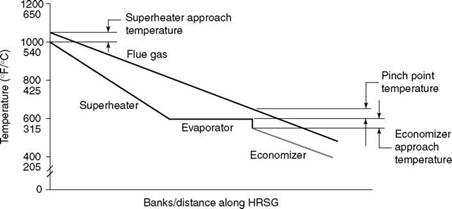
5. Pinch point. As the gases transmit their heat to the EVAP surfaces and get cooled, there is a point below which cooling of the gas demands a disproportionately large surface, making the design expensive. This gap between the gas temperature and the EVAP surface is required to attain optimum HS, which is known as the pinch point. A gap ranging from 8 to 14°C is followed in the present designs. The reduction to the present levels has increased the HS of the EVAP by nearly 100%.
A. Approach temperature. The gap between the ECON outlet and the gas temperature is another important parameter and is known as the approach temperature. It should be between 8 and 14°C. This also ensures that there is no steaming in the ECON. However, with cycling becoming more popular, steaming in the ECON is inevitable. The last tubes would then act as a forced-flow EVAP. Piping from the ECON to the drum should be upwardly sloping to permit a smooth flow of steam. Also, the drum should have separate set of hydroclones.
B. SH approach temperature. The approach temperature for SH is usually between 22 and 33°C (40-60°F) (Table 14.7; Figure 14.16).
6. Multiple boilers in one. Heat recovery steam generator can be conceived as two or three boilers, operating at different pressure and temperature levels, accommodated within a single enclosure.
A. There are at least two levels of operating pressures except in very small units.
B. In power cycles of 100 MWe and above (Fr 6FA), three levels are common.
C. The pressure levels are designated as HP, IP, and LP denoting high, intermediate, and low, respectively, and usually utilized in the following manner:
I. High-pressure steam is for power generation. High pressure level has steadily gone up to 170 bar for large turbines such as 9FA and the final SH and RH steam temperatures to 570°C.
Ii. Intermediate-pressure steam is for power generation and also for steam injection into the GT. The IP levels are generally 25-35 ata and up to 450°C. In RH boilers, IP steam is added to the RH steam from the turbine.
Iii. Low-pressure steam is for heating the condensate or for deaeration at —3 to
6 bar.
|
Surface |
Approach Temperature °C °F |
||
|
Economizer |
8-14 |
14-25 |
|
|
Evaporator |
8-14 |
14-25 |
Pinch point |
|
Superheater |
22-33 |
40-60 |
|
FIGURE 14.16 Typical temperature profile of heat recovery steam generator (unfired). |
7 For 300 MW and above (Fr 9FA), RH is also employed. Unlike in power boilers, the RH steam flow is higher in HRSGs, as the IP steam is also generated at the same pressure and added to the RH flow.
8. Low gas exit temperatures. The gas exit temperatures of HRSG are usually much lower than those in conventional boilers, as the condensate is directly fed to the preheater of the HRSG from the condenser at —30 to 40°C. For gas firing with no sulfur, an exit temperature as low as 75-80°C can be adopted, with the metal temperature kept at 55-60°C by recirculating the condensate. With sulfur in fuel, depending on the sulfur content, a suitable exit temperature has to be chosen to avoid corrosion of tubes, based on limits given in Figure 6.36. The extent of the gas cooling to attain a low exit temperature is dependent on the fuel costs.
9. Swell in EVAP tubes. The HRSGs are exposed to a severe and abrupt heating, particularly when the GT starts and the exhaust gases enter the HRSG. The EVAP tubes generate steam very quickly, which finds its outlet into the respective steam drums, causing the water to rise to levels that can cause carryover. The drums are to be sized for providing adequate volume to take care of the swell. Simpler internals such as deflection baffles and demisters are better than vertical cyclones, which occupy more space. The swell effect is more pronounced in vertical designs in which the EVAP tubes are arranged in coil form as opposed to individual short tubes in the horizontal design. The coils tend to accumulate steam and discharge into the drum, causing a bigger swell in vertical design. The vertical designs may demand larger drums, particularly if there is no bypass stack.
10. Superheater and RH tube materials. Materials used in conventional boilers are used in HRSGs as well. Even for high steam temperatures such as 570°C, T91 is adequate. Stainless steel is not suitable because:
A. The long HRSG tube lengths, subject to much higher elongation with ss (30% more than other steels), create differential expansion.
B. Since tube metal temperatures are only —35°C higher than the bulk steam temperature with no radiant heat, T91 is quite adequate.
C. The fear of stress corrosion cracking is always present with ss.
The fin material must be a high Cr-Ni steel to withstand high gas temperature.
11. Attemperator. There is no need for attemperation in an HRSG. However, attempera — tors are provided at final SH and RH to limit the temperatures and protect the tube materials from excessive temperature during the cycling duty. Providing hot water from ECON exit instead of cold condensate is gaining acceptance to eliminate the thermal shock.
12. Feed water regulator (FWR) downstream of ECON. During cycling, steaming of the ECON is inevitable. Particularly in vertical HRSGs, steaming upsets the flow of feed water to the drum, as the direction of water flow is downward. By locating the FWR downstream of the ECON, full pump pressure is made available in the entire ECON, reducing the chances of steaming.
1. Bank depths. Considerations are nearly the same as in conventional boilers. The depths are limited to —3 m from access requirements. There is no soot blowing requirement in HRSGs.
2. Tube and casing clearance. With the tube banks tightly packed with finned tubes and gases flowing at high speeds, the gaps between the end tubes and casing assume great importance. Unless they are properly closed, gas bypassing can sharply reduce the performance.
3. Soot blowers. Soot blowers (SBs) are rarely installed, as the gases are usually clean. With certain fuels such as kerosene, there may be fouling of banks by soot. Soot deposition can be predicted by Bacharach index of the fuel, but previous experience can determine the need for SBs.
4. Insulation. In HRSGs the insulation can be on (1) the inside (hot casing), (2) the outside (cold casing), or (3) on both sides. With no water-cooled membrane panels, the hot gases directly contact the casing. In smaller HRSGs, where the exhaust gas temperatures are lower than —480°C, MS casing with external insulation can be adopted. The method for higher gas temperatures is insulating the casings from inside and securing by alloy liner plates. As the gases cool down after a few banks, it may be possible to adopt insulation from the outside. Glass and slag wool are usually limited to 500°C and sometimes up to 650°C in blanket form. In fire ducts with supplementary firing, the gas temperatures range from 900 to 950°C and require ceramic fiber blankets.
5. A weather damper between the last bank and the stack is typically an HRSG feature. Weather damper is a pair of eccentrically supported semicircular halves that close automatically when the upward flow of gases ceases. It prevents ingress of water from rain or snow into the unit to avoid corrosion of internals when it is stopped for long periods. Dampers are extremely useful in conserving the heat
When the unit is taken off the range for short periods. As cycling of the HRSGs is gaining importance, weather dampers are considered essential for horizontal units as well. Also refer Section 7.3.2.4 for some more details.
6. Duct burners or in-line circular burners are employed for firing supplementary fuel. Because minimal upstream duct is provided, flow straighteners in the form of perforated plates are used. For more details about duct burners, refer to Section 10.3.
7. Fire duct. Design is complex, more so in the horizontal design. The footprint of the duct and the length of the HRSG can be minimized by increasing the slope of the fire duct roof consistent with the filling of the duct with gases. This is usually monitored by flow modeling or data from previous installations.
8. Stack is an integral part of the vertical HRSG and independent in the horizontal design. With natural gas firing, the stack height for gas dispersion is not a consideration. The stack must be higher than the surrounding buildings. However, as the gas volumes are very large, the stack velocities are higher in 20-25 m/s range to reduce the diameter. As the gas temperatures are low, —80 to 120°C, the stack is usually insulated from the outside to avoid condensation of moisture, which can cause corrosion.
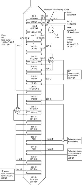
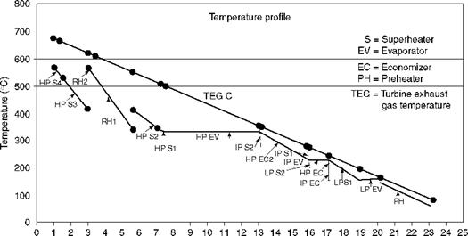
A typical heat balance diagram (HBD) and the temperature profile graphs are depicted in Figures 14.17 and 14.18.
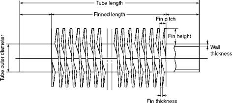
Finned tube is the raw material for HRSGs. The progress achieved by HRSGs could not have been possible without the development of finned tube making. Figure 14.19 shows a typical finned tube.
A strong tube-to-fin bonding is the basis an HRSG.
• Start-up conditions when the bypass stack is not ahead, impose the most severe duty on any boiler tube, as the GT exhaust gases abruptly enter a cold unit and reach 60-70% of their full temperature in —5 to 10 min. Unless the bonding between the tube and the fin is robust, the differential temperature would loosen the fins.
• For predictable heat-transfer rates and strength, the uniformity of bonding between tubes and fins is also highly important.
High-frequency resistance-welded fins alone can withstand the conditions and are the only recommended types today.
Plain tubes among the fin tubes. The HRSG is entirely made of fin tubes except for the front tubes of the RH and the final SH, where containing the fin temperature due to high gas and steam temperatures can be difficult. Also, for achieving desired steam temperature, plain tubes are required as the additional HS of the fins may not be required. The remaining tubes are finned.
• Fin thicknesses vary from 0.8 to 1.5 mm.
• Maximum pitching can be as high as 310 fins/m with 0.8 mm fins.
|
FIGURE 14.17 Heat balance diagram of triple-pressure and reheater RH (3P + RH) heat recovery steam generator behind 9FA gas turbine. ECON, economizer; EVAP, evaporator; HP, high pressure; IP, intermediate pressure; LP, low pressure; RH, reheater; SH, superheater. |
|
Heat exchangers FIGURE 14.18 Temperature profile for heat balance diagram of triple-pressure and reheater (3P + RH) heat recovery steam generator behind 9FA gas turbine. |
|
FIGURE 14.19 Finned tube. |
• Heavy fins are for heavy fuels, and thin fins are for gases.
• Maximum height of the fin is governed by the cooling effectiveness of the steam or water inside the tubes. Normally fin height is limited to 15 mm.
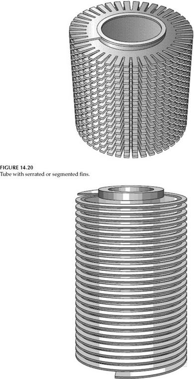
• Serrated and solid fins are the two types.
— Serrated fins provide more heat transfer surface for the same size and are cheaper. Unfortunately, they are suitable only for clean fuels that leave no deposits between serrations, which reduce the heat transfer. More than 90% of the HRSG is built with serrated fin tubes with clean gases (Figure 14.20).
— Solid fins. Even with clean fuels the final SH and RH sections are made of solid fins, as the fin cooling is better (Figure 14.21).
|
|
Tube material selection is governed by the metal temperature limits specified by the applicable boiler construction codes. Tube metal temperatures, in the absence of radiation from flames, are —10°C higher than the bulk water temperature for ECON and EVAP tubes, and —35°C higher than the average steam temperature for SH and RH. Although common tube materials in conventional boilers are adequate for HRSGs, the high fin temperatures (half way between the gas and the tube temperatures, depending on the fin thickness, height, and cooling effectiveness of the fluid in the tube), require superior metallurgy. The usual fin materials and their limiting temperatures are given in Table 14.8. Normally any combination of tube and fin can be made in this range because the welding poses little difficulty.
The most important dimension of the HRSG is the tube length that decides the length and height of the unit. The intent is to increase it to the maximum, consistent with the ability of the exhaust gases to sweep the entire length properly and prevent performance shortfall. Gas velocities of —15 m/s are employed to balance the pressure loss and good heat transfer. The resulting tube lengths are roughly as given in Table 14.9. The width of the unit automatically follows this. The site location, erection procedures, and transportation limits are also factors. For the largest HRSGs, tube lengths as long as 26 m are employed.
The finned tube lengths are given in Table 14.9 and actual tube lengths will be a little larger.
|
TABLE 14.8 Fin Materials and Limiting Temperatures
|
|
TABLE 14.9 Typical Tube Lengths (Finned) of Heat Recovery Steam Generators |
||
|
Gas |
Approximate Gas Flow |
Approximate Finned Tube |
|
Turbines |
(tph) |
Length (m) |
|
LM6000 |
463 |
9 |
|
Fr 6B |
505 |
9 |
|
Fr 6FA |
713 |
12 |
|
Fr 9E |
1456 |
15 |
|
Fr 94.2 |
1793 |
18 |
|
Fr 9FA |
2526 |
20 |
|
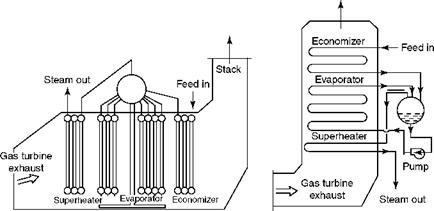
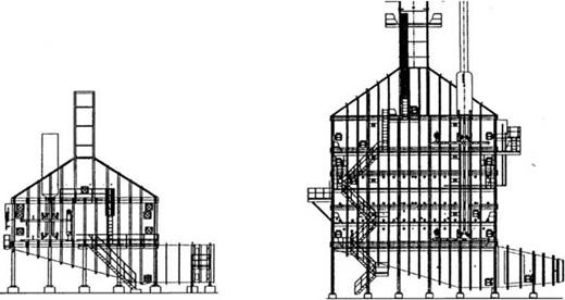
FIGURE 14.22 Horizontal and vertical heat recovery steam generators. |
Two types of designs have evolved.
1. The horizontal design with natural circulation in the United States
2. The vertical design with forced or assisted circulation in Europe
The direction of the gas flow determines the nomenclature. Consequently, a vertical
HRSG has horizontal tubes and vice versa. Horizontal and vertical HRSGs are shown in
Figure 14.22.
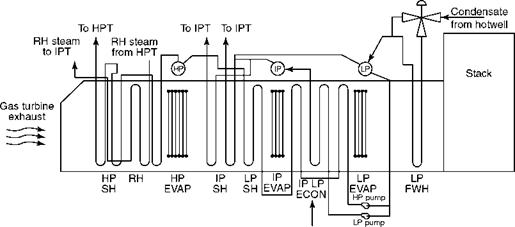
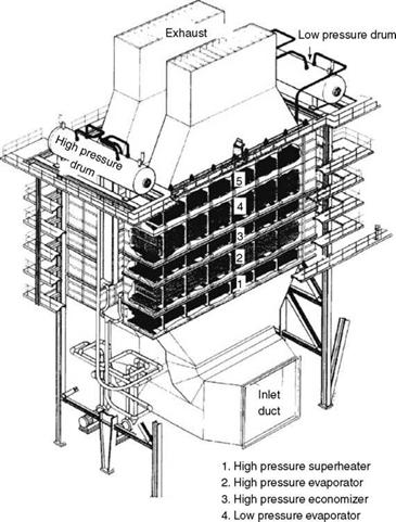
Figures 14.23 and 14.24 depict a typical horizontal HRSG.
• The horizontal design provides natural circulation under all conditions of operation. The circulation ratio is ~6 or 8:1 in the HP circuit and even higher in the IP and LP circuits.
• The design is simple, and the supporting structure is light, with fewer platforms.
• The stack is supported from the ground with no load on the structure.
• Erection is simpler, and requires less time.
• The tubes are bigger in diameter—normally 38, 44.5, 50.8, and 63.5 mm (1_, 1_, 2, and 2_ in.) OD. The heat-transfer coefficients are comparatively lower, resulting in a greater surface and thicker tubes. Thus, the overall tube weight is more.
• The swell effect is not similar to that of vertical units where the tubes are continuous loops and the accumulation of steam from all the legs takes place before discharging into the drum. Hence the drums can be comparatively smaller.
• It occupies more floor space. If a catalyst for NOX control is also included, the footprint increases.
• With headers on both top and bottom, there is a limitation on the ability of the tubes to expand freely and quickly as needed for cyclic operation. Designs now
|
FIGURE 14.23 Triple-pressure and reheater (3P and RH) unfired horizontal heat recovery steam generator. ECON, economizer; EVAP, evaporator; FWH, feed water heater; HP, high pressure; IP, intermediate pressure; LP, low pressure; SH, Superheater. |
Minimize this problem. But inherently they are less flexible and hence less suited for cycling duty.
• As the headers are low and the blow tanks are at a higher level, pump assistance may be needed for blowoff and draining.
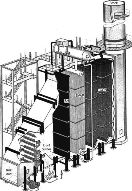
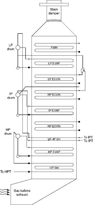
Figures 14.25 and 14.26 depict a typical vertical HRSG.
• European in origin, the vertical design HRSGs employ horizontal coils that are always top supported from the structure to allow free expansion downward. The HS modules are suspended by suspension tube sheets.
• The tube sheets are pin-jointed to allow free lateral and downward movement. Further, the holes in the tube sheet are larger by —2 mm than the finned tubes, permitting a free tube expansion. With three-dimensional movement, the flexibility for expansion is very high.
• The headers are all located outside the gas path. The connecting tubes to the header have 90° bends to enhance the flexibility.
• The vertical design, with long horizontal tubes and low circulation ratios of 3 to 1.9:1 in HP circuit, requires assistance in circulating the water. Circulating water pumps were routinely provided. Currently, no pumping is required up to —130 bar design pressure. During startup, however, induced circulation requires the help of a boiler feed pump (BFP).
• The safety margin is somewhat low.
• A vertical design is more compact in plan area. It is taller.
• The structure is heavy, as the load of the tube banks and the stack has to be supported. The wind loads on the stack are very heavy. The platforms are also heavier because the unit is taller.
|
FIGURE 14.24 Single-pressure (1P) fired horizontal heat recovery steam generator. ECON, economizer; EVAP, evaporator; SH, superheater. |
• The tube diameters are lower—31.8, 38.1, and 44.5 mm OD. The heat transfer, therefore, is better, and the surface requirement is smaller. The tube thicknesses are also smaller. These factors contribute to a reduced tube weight.
• Reduced tube diameters provide reduced water holding and hence reduced thermal inertia. The serpentine coils permit a free and fast expansion of tubes during
|
FIGURE 14.25 Triple-pressure (3P) vertical heat recovery steam generator. ECON, economizer; EVAP, evaporator; FWH, feed water heater; HP, high pressure; IP, intermediate pressure; LP, low pressure; SH, superheater. |
|
5. Low pressure economizer FIGURE 14.26 Double-pressure (2P) vertical heat recovery steam generator. |
Startups when gas temperatures increase by as much as 350°C in 5 min. This design is inherently better suited for cycling duty.
• Swell effect is felt more in vertical designs as explained in Section 14.3.7.1, calling for relatively larger and hence thicker drums.
• The fin heights are usually <15 mm, yielding high efficiency. Also, vertical fins tend to be self-cleaning in comparison with the horizontal fins.
• With pressure parts (PPs) located —6 m above the ground, the drainage to blowdown tank is by gravity and does not require pumping.
• Construction is more time-consuming and complete modules must be assembled in the shop.
There is no clear advantage of one design. With many leading HRSG vendors making both types, the disadvantages are disappearing. The layout and cycling needs decide the type to be adopted for a particular duty (Figures 14.25 and 14.26; Table 14.10).
|
TABLE 14.10 Comparison of Horizontal and Vertical Heat Recovery Steam Generators
|
System Configurations of Typical HRSGs
Table 14.11 captures the HRSG process configurations in typical CC modes behind some popular GT models. The gas flow is based on NG firing at 15°C. The steam flow and temperature refer to HP, IP, LP, and RH conditions serially.
• The high efficiency of the aeroderivative GT can be gauged by high firing and low gas exhaust temperature [note (1) in Table 14.11].
• Steadily rising exhaust temperatures accompany the increase in the GT size. The exhaust gas pressures are also higher with the increasing GT size, permitting more tube banks in HRSG.
• This makes it possible to adopt very high SOT and inclusion of the RH when the ST is larger than —100 MWe. The gas temperatures are ~570°C in large CCs [note
(3) in Table 14.11].
• In a conventional boiler, furnace exit gas temperature (FEGT) cannot be <1000°C for a final SOT of 570°C; it is only —615°C in HRSGs. The terminal temperature difference is as low as 25°C due to the very high gas quantities of the HRSGs [note
(4) in Table 14.11].
• An SOT higher than GT exhaust temperature is indicative of supplementary fuel firing [note (2) in Table 14.11].
• Power generation is dependent on the ambient conditions.
Once-Through Steam Generators (OTSGs)
Subcritical once-through flow is an advanced version of the HRSG, which requires no drums, risers and downcomers, blowdown system, etc., associated with circulation. There are no distinct ECON, EVAP, and SH sections; water enters the coil and comes out as steam. Therefore, the various tube sections and headers comprise a single bank. As the cooling
|
Process Parameters of Heat Recovery Steam Generators (HRSGs) in Various Combined Cycle Plant Configurations
|
|
646 Boilers for Power and Process |
![]()
TOC o "1-5" h z General Fr 9FA 2526 701.7 610 (3) (4)
Electric
Mitsubishi 701F 2347 651.9 591 (3) (4)
Siemens SGT 5^000 F 2420 672.2 582 (3) (4)
(94.3 A)
Note: Numbers (1^1) given in parenthesis are notes that are explained in Section 14.4.10.
|
322 |
89.44 |
129 |
568 |
400 |
|
28 |
7.7 |
41.5 |
320 |
|
|
17.7 |
4.92 |
6.4 |
237 |
|
|
332 |
92.22 |
39.4 |
568 |
|
|
324 |
90.00 |
127 |
568 |
390 |
|
40 |
12.27 |
27 |
339 |
|
|
32 |
8.89 |
5 |
260 |
|
|
361 |
100.28 |
26 |
568 |
|
|
271 |
90.33 |
124 |
540 |
400 |
|
46 |
12.78 |
37 |
568 |
|
|
42 |
11.67 |
6 |
251 |
|
|
311 |
86.39 |
36 |
568 |
|
|
299 |
83.06 |
130 |
567 |
400 |
|
55 |
15.28 |
32 |
320 |
|
|
39 |
10.83 |
4 |
234 |
|
|
328 |
91.11 |
31 |
565 |
|
Waste Gas Firing 647 |
![]()
|
FIGURE 14.27 Once-through steam generators versus heat recovery steam generators. (From Innovative Steam Technologies, Canada. With permission.) |
Effect of steam is substantially less, the tubes are made of very high temperature-resistant materials such as Inconel alloys. OTSG permits dry running of the unit, dispensing with the bypass stack. OTSGs are made in vertical design. Figure 14.27 compares an OTSG with an equivalent HRSG.
OTSGs are slightly more efficient than the HRSGs, as the preheater gas outlet temperature can be lowered without the fear of low-temperature tube corrosion because the tubes are made of Inconel. Also, the gas leakage in the bypass stack is not an issue.
The boiler PPs are significantly lighter and compact. The structure is also lighter. The space requirements are slightly lower. The instrumentation and control needs are fewer as a single feed control valve at the inlet varies the output. The construction time is lower.
The tube bank of Inconel makes OTSG more expensive than HRSG. Where compactness and less weight are important such as in a barge-mounted plant or a marine application, OTSG provides a unique solution. Also, where it is highly beneficial to shorten construction time, OTSG can be considered favorably. OTSGs are confined to —60 tph steam output behind smaller turbines such as LM6000 or Frame 6 or Trent. In large conventional plants, the HRSGs are preferred.
There are major differences in approach in testing of conventional boilers and HRSGs. A brief description appears in Section 1.6.6.
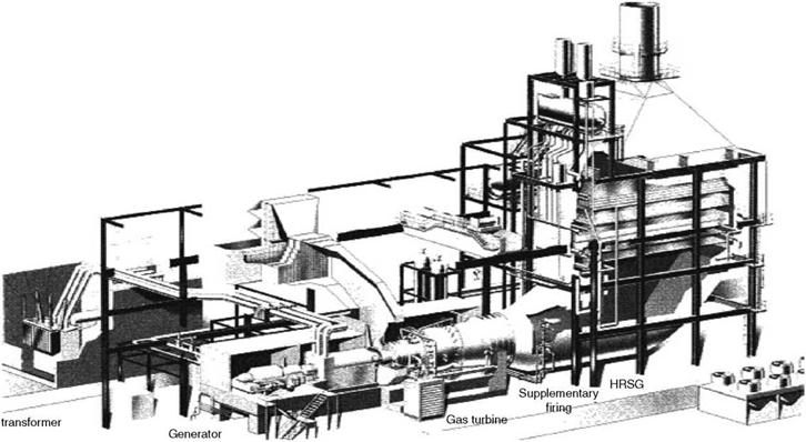
A typical layout of a CCPP with vertical HRSG is shown in Figure 14.28.
|
Waste Gas Firing 649 |
|
|
|
|
Further Readings
Boissenin, Y., 1990, Combined cycle power plants: A practical guide to right choice, Ahlstrom, Urja, May.
Collins, S., 1994, Gas turbine power plants, A special report, Power, June.
Fontaine, P., 2002, Cycling tolerance—Natural circulation vertical HRSGs, ASME Paper IJPGC 200340114, HRSG User’s Guide, Power, October.
Innovative Steam Technologies, OTSGs, Cambridge, Canada.
Makansi, J., 1990, Combined cycle power plants, A special report, Power, June.
Makansi, J., 1994, HRSGs, steam turbines and auxiliaries for combined cycles, Power, September. Makansi, J., 1998, Gas turbines, A special report, Power, March.
Nessler, H. et al., 2001, Developments in HRSG technology, MAB Anlagenbau Austria Gmbh, Presented at the GT O&M Conference, UK, November.
Nestianu, D. et al., 2003, Vertical or horizontal? An EPC contractors’ angle, Modern Power Systems, March.
Pasha, A. and Allen, R., 2003, Designing and modifying HRSGs for cycling operation, Vogt-NEM Inc., Power, March.
Peltier, R. V., 2001, Special report on advanced gas turbines and HRSGs, Power, September-October. Pequot Publishing, Inc, 2006, Gas Turbine World Handbook.
Scheibel, J., 2004, Designing and operating HRSGs for availability, EPRI, Power, January-February. Smith, D., 2004, GTCC competitive, Modern Power Systems, August.
Smith, D., 2004, H system steams on, Modern Power Systems, February.
Swanekamp, R., 2002, Raising the reliability of gas turbines, a special report, Power, March-April.


 14 сентября, 2013
  admin
admin 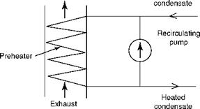
 Опубликовано в рубрике