Grate burning can be classified as (1) mass burning (MB) and (2) spreader burning (SB), depending on whether the fuel burns on the grate or partly in suspension and partly on grate. There are two designs each for MB and SB. The spreader stokers (SS) are the most common.
1. MB with gravity feeding
A. Chain or traveling grates (CG/TG)
B. Reciprocating or pulsating grates (RG/PG)
2. SB with spreader feeding
A. CG/TG
B. Dumping grates (DG)
Other types of grates for wood and bagasse firing are
• Pinhole grates (PHGs) for low- and high-moisture fuels (up to 55% moisture)
• Inclined water-cooled grates (IWCGs) for even higher-moisture fuels (up to 70% moisture)
Both are stationary grates, and combustion is by pile burning. They are discussed in detail in Chapter 9.
Based on the type of feeding, the stokers are classified as follows:
• Underfeed stokers
• Overfeed stokers
Underfeed stokers have both coal and air feeding from the bottom of the grate and ash discharging from the sides. The boiler capacities are very small for single — and doubleretort stokers. Multiple-retort stokers can be built in large sizes. This type of stoker has practically disappeared from industrial use, surviving only in small pockets for niche applications, where good coal is available.
Overfeed stokers have coal feeding from the top of the grate and air from the bottom. Mass burning and SB are the two principles of overfeeding, where mass feeding is by gravity and spreader feeding is by throw. Even in overfeed stokers the gravity-fed MB boilers now have very little market, but many units were built to fairly large sizes when the coals were good. But the overfeed SS, with either over — or under-throw design, with substantial combustion in suspension is more versatile and enduring. Spreader stokers can be combined with any grate—CG/TG, DG, and RG/PG. Table 11.1 lists the workings of the various grates.
There is practically no solid fuel that cannot be burnt satisfactorily in a stoker. Table 11.2 examines the compatibility of the various stokers and fuels.
Among all the systems SS, with suspension firing, is exceptionally versatile, flexible, and dynamic and hence became the workhorse of the industry and small utilities by the 1930s. Well into the 1960s, SSs were employed in the utilities for units up to 50 MW and even higher with good coals. The largest SS-fired boiler built appears to be 80 MW on lignite. As the average sizes for the utility units grew, the SSs were left behind. Pulverized
|
TABLE 11.1 Workings of Various Grates
|
|
TABLE 11.2 Compatibility of Grates for Various Fuels
|
Fuel (PF) was for utilities, and SSs for captive and cogen power and process steam were prominent for decades. The position started to change only in the 1980s because of the following four factors:
1. Deteriorating quality of coals across the globe, along with hardening of prices. Stokers demand good quality coals with proper sizing, as the performance is very sensitive to size, fines, and ash. They are also not capable of dealing with much sulfur in fuel.
2. The emerging pollution norms were beyond the ability of stokers to meet effectively and efficiently.
3. More efficient technology in the form of FBC, which is also more fuel-flexible and ecofriendly. The low-temperature combustion and in-furnace desulfurization answered the pollution issues.
4. Larger sizes required by utilities.
Although the reign of the stokers has practically ended for coal firing, interest in
• Firing of ecofriendly biofuels worldwide
• Bagasse-based cogen in tropical regions
• Woodchips-based power generation in temperate climates
• Municipal refuse firing worldwide
Is giving a fresh life to stokers. Biofuels do not contain sulfur (<0.1°%) and the fuel moisture depresses the combustion temperatures; hence, the formation of SOx and NOx is no longer the issue. At the same time, biofuel is an area where FBC is not strong as most fuels are too light and fluffy to work well and present no advantage in combustion efficiency. Further, as necessary ash is not present in the fuels for bed replenishment, the arrangement works out to be comparatively expensive. Stokers present an elegant and economical solution in this growing market, although the present situation cannot be compared with the former good times.
Although stokers are employed primarily for biofuel firing, coal firing is practiced on stokers for auxiliary and supplementary or alternate fuel duties as biofuel availability is seasonal and shortfalls are normal.
The following points are common to all designs.
The grate and stoker terms are used interchangeably in the industry. Grate is the flat bed at the furnace bottom, which is either stationary or moving, on which the fuel burns. When combined with the fuel distributors it becomes a stoker. Fuel distributors for spreading the fuel on grate are also called stokers.
Solid fuel is delivered by gravity or flight, and air is admitted mainly from below the grate to burn the fuel. Part of the air is delivered above the grate for burning the volatiles and fines. The ash is conveyed to the ash pit. The grate or bed firing burns slowly on the grate and suspension firing burns vigorously above the grate.
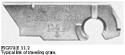
These two terms are also used interchangeably in the industry. In CGs the individual stoker links (Figure 11.1) transmit the chain forces and experience the tensile loads caused in the movement of grate. In the TGs, the stoker links (Figure 11.2) rest on bulb or T-bars, which are attached to the chains experiencing the loads. The grate bars are not subject to any forces.
|
FIGURE 11.2 Typical link of traveling grate. |
 As the grate bars are not under load, it is possible to build TGs of larger size. Chain grates tend to be lighter and more rigid because the additional members such as bulbs and T-bars are not present. But the links of the CG have to be stronger to withstand the forces of transmission. The big advantage of TGs is the ability of the links to break loose and dangle
|
FIGURE 11.1 Typical link of chain grate. |
Vertically in the return travel, making it possible for the ash to drop into the hopper below. Tip and jolt bars are added to further scrape the top surface.
Using Same Grate for Mass and Spreader Burning
The grate carries the fuel through the various burning zones until the combustion is complete. It is advantageous to have the same stoker construction for both types of firing provided the following conditions are met.
• The combustion processes differ based on fuel bed thicknesses requiring different air-pressure drops in the grate, 55 and 40 mm w. g. (2 M and 1 V in. w. g.) for mass and spreader, respectively. The grate link construction has to be modified to reduce the area exposed to air.
• In most cases the stoker has to travel forward in SB and backward in MB.
Some grates can work with both types of feeding.
Moistening of Coal before Firing
In all types of stokers it is necessary to moisten the coal so that it forms a loose lump when pressed. This would correspond to ~10% free moisture. This moistening is done on coal conveyors in the yard or the coal chutes or both. Water and steam sprays are both employed. The purpose of moistening is to
• Make the coal bed porous by streams of steam (formed on water evaporation), to improve combustion quality.
• Make the coal fines stick to the lumps so that they burn. This improves the combustion efficiency by better burning and reduced unburnt loss and minimizes dust.
Clinker is the molten ash slag that accumulates coal and ash particles on its surface and turns into a lump. Clinker is a nightmare to any boiler operator. Ash fusing at high temperature and forming small clinker toward the discharge end of a grate are normal to an extent and cause no disruption. But when it grows in size and disturbs the grate operation, a chain reaction promotes more clinker and there can be total disruption of fire.
Melting of ash, which is the root cause of clinker formation, arises from
• High alkali content of the ash, which results in low ash-melting temperature.
• Presence of reducing conditions that depress the melting temperature of normal ash (see Figure 3.12) due to low amounts or poor distribution of air.
• High-swelling coals that swell disproportionately and agglomerate in plastic condition, disrupting the air distribution pattern and creating reducing conditions.
• High fines in coal that attach themselves to the burning coal whose ash is in a semimolten state.
• Agitation of actively burning coal bed. This makes the semimolten ash spread and hold other coal pieces, fines, and ash particles to form a lump, which disturbs the bed conditions and keeps growing. Reciprocating grates are not suited for coals for this reason. Even nonagglomerating coals clinker with bed agitation.
• Segregation of coal across the width of the bed resulting in an uneven distribution of coal and air, resulting in patches of air leading to reducing conditions.
• Uneven coal flow and airflows in the grate, which creates conditions similar to segregation.
• One-sided entry of primary air (PA), shallow ash-air hoppers, substoichiometric conditions, and improper air seals leading to reduced conditions in the bed.
Clinker formation leads to disturbance in steam generation and consequential losses. Segregation of coal, high percentage of fines, and air-fuel mismatch are the issues that may need correction. Ash and coal properties are to be checked next.
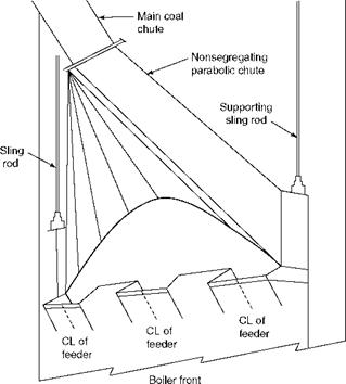
In coal crushing and subsequent sizing, generation of fines is natural. But separation of fines and large pieces adversely affect the combustion efficiency in any stoker, and every effort is needed to prevent such separation. This separation is found to take place as coal travels from bunker to hopper. The following two methods help in achieving even distribution of coal:
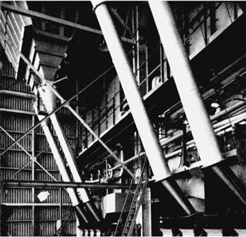
1. Traversing chute (Figure 11.3) spanning the width of the hopper so that the coal is evenly fed.
2. Antisegregation chute (Figure 11.4) where coal is made to travel from the inlet to the outlet on the bottom plate of a parabolic chute so that the fines and lumps spread evenly. The bottom of the chute is bolted to the coal hopper in front of the boiler.
The traversing chute is the better in terms of even distribution of coal but involves more complicated construction and more headroom.
Smooth flow of coal from bunker to hopper without any hang-ups is very important. This is ensured by keeping the inclination of the chutes at >60° to the horizontal. Steam connections for coal moistening are installed at the top of the chutes with the help of ~6 mm connections at the bottom side. For abrasive and moist coals, causing wear and rust, respectively, the chutes are made of stainless steel (ss). Glass lining of the traversing chutes is another popular method.
Coal sizing is perhaps the most important characteristic affecting the performance of stokers. When coal is naturally crushed, fines are generated. Every coal transfer during the transport from mine to yard adds to the fines. As the coal enters a power plant, it appears
|
|
FIGURE 11.3
Traversing chutes.
|
|
As a combination of lumps and fines of varying sizes. Fines are substantially sand particles and hence are troublesome as they
• Erode fuel-handling equipment such as chutes, feeders, distributors, and pressure parts (PPs)
• Promote clinker formation
• Increase the unburnt losses and reduce boiler efficiency
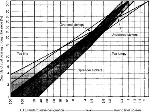
The lumps need more time to burn, and unless the top size is limited, the combustion would not be complete. The sizing is different for different stokers. Mass burning can accept larger top size but is less tolerant to fines. Spreader firing needs smaller top size to limit the wall impingement forces but can take more fines than MB because of suspension firing, but the performance deterioration is rapid as the fines exceed the limit. Stoker manufacturers generally follow the ABMA recommended graph for the sizing of coals for various types of grates. See Figure 11.5.
• The upper and lower curves are the limits for nonfriable and friable coals, respectively. As the friable coals break down quickly, due to the expansion forces of their moisture, higher coal sizes are permissible.
|
Approximate mm equivalent.075 0.3 0.6 1.2 2.4 4.8 6 10 12 20 25 32 50
|
• Coals right to the bottom curve are too lumpy for proper combustion. Likewise the coals left to the upper curve are too fine to be acceptable.
• Coals are to be delivered across the grate in a uniform sizing without segregation.


 6 сентября, 2013
  admin
admin 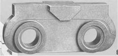
 Опубликовано в рубрике