Suction and Pressurized Milling
In suction milling, the exhauster fan is located between the mill and the boiler. It pulls the hot air from the AH outlet through the mill and picks up the ground coal from the mill to deliver the mixture to the burners.
Hot air is suitably mixed with ambient air to meet the mill outlet temperature requirement. The mill and feeders are under suction and this helps keep the area clean. The exhauster always handles cold (mill outlet temperature), wet (moisture from coal), and dust-laden air with a compact radial fan. The fan maintenance is likely to be heavy unless the coal is very soft (which is normally associated with high GCV), requiring less fuel.
The pressurized milling is more popular because there is no exhauster maintenance, along with other benefits. The primary air (PA) fans are located upstream of the mills; therefore, the milling plant is always under pressure, requiring good sealing to prevent a dusty environment. The PA fans can be placed
1. Immediately ahead of the mills, usually one for each mill. The hot fans take suction from the AH outlet.
2. Upstream of the AH the fan deals with ambient air. Two fans can supply air for all the mills.
A trisector rotary AH can be considered. In both cases, there is mixing of ambient air from the forced draft (FD) fan to suit the drying needs of the mill. The least fan power option is usually adopted.
Feeders and mills are required for a throughput of 20-100 tph and two types of feeders are available:
1. Belt type
2. Chain type
A feeder is a volumetric device. By providing a fuel weight measurement, the belt feeder can be made into a gravimetric feeder. This is not possible with a chain feeder. When the mill feeding rate must be handled individually for boiler-control purposes, the gravimetric feeder is desired. Otherwise volumetric feeders are used even for very large boilers.
To meet the National Fire Protection Association (NFPA) requirements, the feeder casing should be of 6 mm size, and the housing should be cylindrical.
The feeder shown in Figure 13.3 employs an endless belt on which coal descends from the bunker at one end and discharges into the mill at the other end. The feeding rate is varied by the speed of the driving roll. Gravimetric feeders have gained a lot of acceptance because of their accuracy and reliability. The feeders usually come in lengths of 2.1 and
|
|
|
Coal Bunker
FIGURE 13.4 Drag link volumetric chain feeder. |
3.6 m (7 and 11 ft) and widths of 750, 900, 1050, and 1200 mm (—30, 36, 42, and 48 in.). American designers usually prefer gravimetric feeders.
Chain Feeders
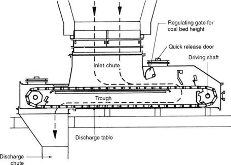
The drag link chain feeder shown in Figure 13.4 can be described as a pair of forged chains riding on a pair of sprockets on the drive and driven shafts and connected by links to drag the coal. Coal from the bunker, landing on the upper plate, is dragged to the drive end that is away from the mill and dropped to the bottom plate or discharge table. Then it is dragged along the bottom plate to the mill. Usually the feeders come in widths of 600, 800, 1000, and 1200 mm, handling —40-130 m3/h (30-100 t) of coal.
A set of coal mills or pulverizers is the
• Most expensive part of a PF boiler
• Most power-consuming
• Highest maintenance area
• Heaviest single item
The reliability of the milling plant practically governs the availability of the boiler. It will not be an exaggeration to say that the mills are the most important parts of the PF boiler, as they decide the cost, performance, auxiliary power, and layout of the total plant.
Mill duty.
• Grind coal
• Evaporate moisture
• Classify fines
• Discharge acceptable fine powder pneumatically
Modern vertical mills combine all these four functions inside a single housing.
Mill requirements.
• Capability to handle a wide variety of coals
• Accommodation of load swings
• Optimum fineness throughout the mill operating range
• Low wear rates of the grinding elements
• Low noise levels
• Ease of maintenance
• Low O&M costs and low power consumption
• Minimum building volume
Hardgrove index (HGI). The size, output, and performance of a mill are affected by the grindability of coal. Hardgrove index is a measure of the ease of grinding. It should be noted that grinding is not strictly hardness dependent. Fibrous materials are tough and difficult to grind, although they are not hard. The purpose of grinding is to create a new surface by making fines, so that the contact of fuel and air is easy. In other words, grind- ability involves creation of the new surface.
ASTM D409 describes the test procedure in which a predetermined amount of grinding work is carried out on a prepared and sized sample (<16 and >30 mesh) of 50 g of air — dried coal in a miniature pulverizer. After 60 revolutions with predetermined weights, the ground sample is removed, screened, and checked for the quantity passing through the 200-mesh sieve. A calibration chart determines the grindability of the sample.
The value of 50 is considered neutral, and the mill capacities are usually based on 50 HGI. The higher the value, the easier is the grinding. Hardgrove index has no upper limit. The lower the value, the more difficult is the grinding, and the mill capacity is reduced.
Hardgrove index gives a fairly good correlation for bituminous and sub-bituminous coals between the test and the actual results, whereas for lower ranks, the field and laboratory data differ widely due to fuel moisture. Likewise, for high-ash coals, a mismatch is found because of the possibility of mineral accumulation coming in the way of the grinding process.
There are two designs of mills in modern power stations—horizontal and vertical mills.
The two types are:
1. Slow-speed (15-35 rpm) ball mills for hard and abrasive low-moisture coals
2. High-speed (400-750 rpm) beater mills for soft and high-moisture lignites and brown coals
Ball and tube mills were the mainstay of the industry. At present these mills are used for grinding difficult coals, as explained in Section 13.2.1.
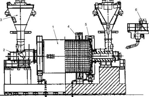
Construction. Ball and tube mills are slow-speed (15-35 rpm) horizontal cylindrical drums with coal entry on one or both sides and external classifiers. Double entry mills are two independent mills with a single housing and drive. Besides economy of space and electrical drives, there are additional benefits. In case of feeder failure, the working feeder can double its input, and the output can be maintained at both ends of the mill. Half mill operation is also possible. Figure 13.5a shows a ball and tube mill, while Figure 13.5b shows the isometric view. Figure 13.7 shows how air and fuel enter the mill from the ends.
Grinding action. Forged balls, varying in size from 25 to 100 mm in diameter, are the grinding medium inside the cylindrical casing protected by bolted manganese steel liners, which last several years. About a quarter of the drum volume is filled with the balls. Grinding takes place by a combination of impact and attrition. The mill speed of —0.8 times gravity is chosen so that the balls climb up the drum to some height before falling back to the bottom and pounding coal heavily to break it down to much finer particles. Hard coals need high impact. The slow grinding of the balls aids in producing finer coal powder. It is easy to understand why the wear of the balls is so great. The balls can be charged into the running mill through the ball-charging door without mill stoppage.
Despite longer residence time in the tube mill due to the absence of a fluidized bed such as in the vertical mill to bring about a vigorous mixing, it is not possible to dry the coal
|
1. Mill body 3. Static classifier 5. Slide shoe bearing 2. Inlet and outlet housing 4. Girth gear 6. Ball-charging device (a) Cross-sectional view |
|
Pulverized Fuel Firing 569 |
|
Ball discharge recovery tray |
|
Drum Double wave drum liner Trunnion bearing |
|
|
|
|
|
|
|
|
|
|
|
|
|
|
|
|
|
|
|
|
|
|
 |
|
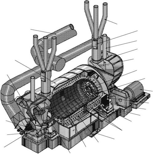
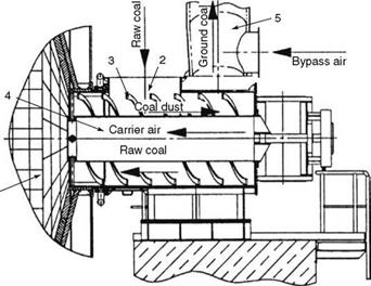
Adequately when it has more than 20% total moisture. Hot mill carrier air, introduced through the central tube of the trunnion, dries the ground coal and carries it through the annular space in the trunnions to the classifiers.
Classification. The double-cone-type classifiers have adjustable vanes to regulate. Classifiers separate the heavy particles and feed them back to the trunnions, where they mix with the incoming coal to reach the grinding zone.
Classifiers are of double-cone construction with wear-resistant liners. Rotating or dynamic classifiers are increasingly employed as the better selectivity returns fewer fines for grinding, thereby reducing recirculation inside the mill.
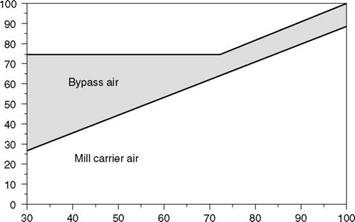
Mill and bypass air. Total PA, consisting of mill carrier air and bypass air, is boiler load dependent. These two airs are mixed separately from hot and cold airs, as the temperatures are different. The mill air quantity is proportional to the mill load, whereas the bypass air increases at low loads to keep up the velocities in classifiers and coal lines. Because of the large amount of coal inside the mill at all times, it is not possible to control the mill output by feeder speed variation as in vertical mills; however, it is possible by the variation of the mill air. The mill outlet temperature is usually maintained between 90 and 140°C (Figure 13.8).
Mill capacity. The maximum fuel flow of a ball and tube mill is proportional to
• The inner diameter of the mill raised to the power of 2.5 (d25)
• Length of the mill (L)
The other factors affecting the mill capacity are
• HGI
• Moisture in fuel
• Fineness desired
• Raw coal size
• Ball filling rate
Fuel inside the mill usually sustains about 15 min of firing at its nominal load, compared to —5 min in a vertical mill.
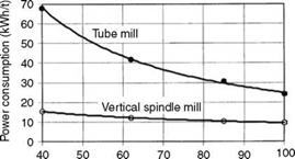
Mill power. The power requirement of the mill is dependent on the mass of the grinding medium and the speed of rotation. So the grinding power is practically constant irrespective of coal flow and the specific power in kilowatt hours per ton of coal at low loads is excessively high. At low loads, however, the fineness of coal increases, rendering the flame very stable.
The ball charge frequency is increased to compensate for ball wear, a very easy remedy. But the plant should be base loaded lest the power consumption becomes excessive. Figure 13.6 gives an idea of relative power consumption.
Advantages and disadvantages of ball and tube mills. Advantages include:
• High availability.
• Easy maintenance. Only periodic ball charge is necessary. Cast liners last for years. (But they need long downtime for replacement.) The maintenance cost over time is about the same as for vertical mills.
• Constant capacity and fineness.
• No effect of foreign material.
• Large reserve capacity and hence quick response.
• Usefulness for hard and abrasive fuels.
|
Specific mill power versus mill load
Mill load (%) |
FIGURE 13.6
Variation of specific mill power with mill load.
The disadvantages are as follows:
• High power consumption, more so at lower loads.
• High-moisture coals reduce output drastically.
• Cost of mill and foundation is high.
• More space is required.
• Redundant mill is usually not possible due to cost and layout.
• High noise levels require insulated enclosures.
• Drying efficiency is low.
• They are not suited for intermittent operation due to chances of fire because of the large number of fines and hot balls inside.
• High-power and high-starting torque motors are required.
Ball mills are employed only in certain special applications beyond the capabilities of vertical mills, as already covered in Section 13.2.1.
• Highly dense and slow-burning fuels with low VM, such as anthracite and petroleum coke, for which the grinding calls for higher fineness, typically 80-85% through 200 mesh (74 |jm)
• High-ash and abrasive coals for which the mills are required to display a superior wear resistance and provide long uninterrupted working between shutdowns
Figures 13.5, 13.7, 13.8, and 13.9 are adopted from internal documents of the former Deutsche Babcock of Germany.
Beater Mills
Beater mills beat soft and young coals unlike grinding the hard coals into powder.
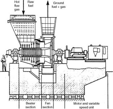
Milling action. These mills are very different from coal mills, both in operation and in design. These are
• High-speed (400-750 rpm) mills
• Designed to use very high-temperature (as high as 1040°C) furnace gases
• For drying very friable and high-moisture (as high as 70%) lignites and peat
|
|
|
1. Grinding space 2. Coal inlet pipe 3. Input screw conveyor 4. Central tube 5. Mill outlet |
|
FIGURE 13.7 Air and coal flows at mill ends. |
|
Fuel mass flow (%) |
FIGURE 13.8
Mill load versus airflows in ball mill.
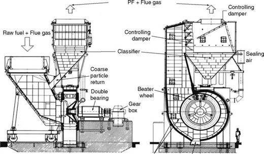
Another important difference is that there is no need for impact for these fuels. Attrition is sufficient and provided by a high-speed beater wheel that works as a suction fan and/or attrition wheel.
Flue gas is used for drying and conveying, in preference to air, as the low-rank fuels have high fuel oxygen, making them susceptible to spontaneous combustion.
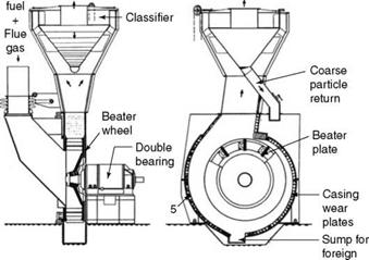
Mill types. There are two types of beater mills:
1. For medium moisture up to 40% (Figure 13.9)
2. For high moisture up to 70% (Figure 13.10)
|
FIGURE 13.9 Beater mill for medium-moisture fuels. |
|
|
|
|
|
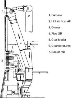
FIGURE 13.11
Air and gas arrangement for beater mill.
The latter types are larger and heavier, as the gas inlet temperatures and volumes are higher. On the discharge side also, the pipes are large, as the fuel moisture is converted into steam, which occupies a large volume. On the whole, beater mills are much bigger than vertical mills.
Milling process. Hot gas from the furnace, suitably mixed with air from the AH exit, enters alongside the fuel, as shown in Figure 13.11. There is flash drying of moisture. On contact with the impeller, the fuel is dry enough to disintegrate into fine powder (Figure 13.11). The mill outlet temperature is between 120 and 200°C and the sizing 50-60% through 90 |jm.
The classifier on the discharge side returns larger pieces to the inlet. The classifier can be of box (Figure 13.10) or centrifugal type (Figure 13.12). The burner and the type of firing and, accordingly, the need for the inclusion of the classifier determine the fineness.
Mill construction.
1. For high-moisture fuels, the construction features of the beater mills are as follows.
A. The impeller is of overhung design, and the inlet box can be withdrawn to permit full access for maintenance.
B. Wear liners are installed on the inlet and outlet sides. The impeller is also provided with liners.
C. Typically
I. The speeds vary from —750 to 450 rpm.
Ii. Mills deliver 35-200 tph of fuel of 60% moisture.
Iii. The mill outlet temperature is —120°C.
|
PF
Matter |
FIGURE 13.12
Beater mill with centrifugal classifier.
Iv. Residue is 50% on 90 |jm mesh.
V. The wheel diameters vary from 2 to 4 m.
Vi. The motor sizes vary from 300 to 1600 kW.
Vii. The specific power consumption varies from 4 to 16 kWh/t.
2. For medium-moisture fuels, the construction features of the beater mills are as follows:
A. The mills are smaller and contain fewer rows of hammer wheels in front of the impeller to provide impact to the relatively harder and nutty lignite.
B. Classifiers may or may not be present, depending on the firing requirements.
C. The rotation of mills per minute varies from 750 to 400.
D. Nominal outputs vary from 10 to 90 tph.
E. The output is based on an outlet moisture of 12% and HGI of 60% with a product fineness of 25% on 90 |jm screen.
F. Motor ratings vary from 250 to 2000 kW.
Figures 13.10 to 13.12 are adopted from documents of EVT GmbH of Germany.
Medium-speed air-swept vertical mills almost entirely dominate the main bituminous coal-firing applications because of their
• Lower power consumption
• Superior dynamics
• Light weight
• Better plant layout
Since they are smaller in capacity, it is also easier to build redundancy to improve plant availability.
Vertical mills in use possess certain distinctive features and advantages.
• These are slow — and medium-speed mills.
• Speed is 20-40 rpm in the larger range.
• Speed is 50-90 rpm in the smaller range.
Milling Process in Vertical Mill
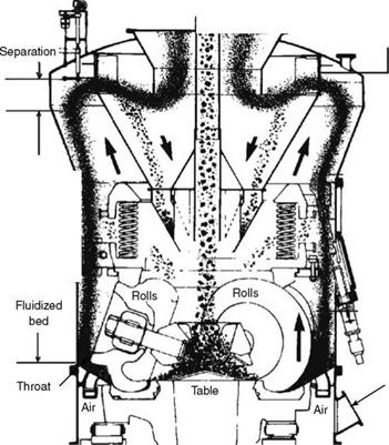
• The coal feeder discharge spout is connected to the inlet pipe located centrally in the mill and discharges onto the rotating table. Thus the crushed coal of <50 mm size lands at the center of the grinding table at the start of the milling.
• Due to the centrifugal force of the rotating table, the coal is thrown toward the periphery where heavy balls or rollers are hydraulically or hydropneumatically loaded from the top, creating top pressure for grinding.
• Coal, continuing its outward travel, gets trapped between the rollers and the bottom plate and is crushed into powder.
• As the powder spills over to the edge, hot PA, admitted from below into the annular space between the table and the outer casing (throat), picks it up and travels toward the classifier. The throat area must be adjusted to impart a high-enough velocity to air such that all the coal powder is floated upward to form a fluid bed.
• This fluidized bed with its intense circulation helps
— Dry the coal within a short height of the fluid bed
— Separate the heavier particles that fall out of the fluidizing zone onto the rotating table.
Thus the primary separation takes place just above the fluid bed zone.
• As the flow continues upward, the height from the fluidized bed zone to the classifiers provides time to complete the drying of the fuel. The two-stage drying, in fluid bed and in freeboard above, is very effective within a short distance, making the vertical mills very good for drying moist fuels.
• Secondary separation takes place above the primary separation zone as the heavier particles drop down due to gravity.
• Tertiary and final separation occurs as the change of direction in the classifier separates the heavier particles and drops them to the bottom plate for further crushing.
• As the powdered coal leaves the table and gets airborne, heavy non-coal pieces, namely stones, shale, and pyrites, fall out of the stream due to density difference in the pyrite chamber. The pyrite plow promptly pushes them into the pyrite box, which is periodically emptied to prevent a fire hazard.
Coal recirculation ratio is the amount of coal in circulation divided by the coal output. The coal-air mixture now leaves the mill for combustion. Figure 13.13 explains the process in detail.
Mill Control
The feeder controls the output. The mill regulates
1. The fineness of the ground coal
2.
|
Coal In |
![]()
|
Classifier |
![]()
|
Tertiary final |
![]()
|
Secondary gravity |
![]()
|
Primary air inlet |
![]()
|
FIGURE 13.13 Grinding process in vertical mill. |
![]()
|
 The outlet temperature of the coal-air mixture
A. The classifier vane position determines the percentage of fines. Once set, it is not altered, unless a change is required.
B. Varying the tempering air varies the mill outlet temperature. The variation of the quantity of the tempering air is a continuous process to keep the mill outlet temperature constant for a certain coal.
C. The usual safe mill outlet temperatures for various fuels are given in Table 13.1. Maximum and minimum mill outlet temperatures are 110 and 66°C (230 and 150° F). The upper limit is set by the limiting temperature of the seals in PF piping and the lower limit by the possibility of condensation of moisture in fuel pipes. The VM in fuel indicates the tendency of premature ignition, which accounts for the lower mill outlet temperature for high VM. These temperatures are adjusted based on actual fuel characteristics and previous experience with the fuel.
13.3.3.2.1 Mill Performance Parameters
Fineness of the ground coal is expressed as the percentage passing through the specified standard mesh, which is usually 200 for coal with a nominal aperture of 75 |jm.
|
TABLE 13.1 Indicative Mill Outlet Temperatures for Various Coals
|
|
Screen aperture (|im) 30 50 70 90 200 400 600 800 1000
|
U. S. Standard sieve designation
FIGURE 13.14
Ringleman chart.
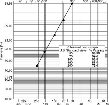
A Ringleman chart (Figure 13.14) is used to find the particle distribution for the other sizes when any one is specified.
Fineness required in general for various coals (through 200 mesh) is
|
60% 70% |
![]() Sub-bituminous coals and lignites with high VM Bituminous and sub-bituminous coals with normal to high VM
Sub-bituminous coals and lignites with high VM Bituminous and sub-bituminous coals with normal to high VM
• High-GCV low-volatile bituminous coals with fixed carbon (FC) of 78 to 86 80%
• Anthracites, pet coke, and so forth with FC of < 98% 100%
Approximately <2% is to be retained on 50 mesh (297 |jm).
In suspension firing, it is necessary that the fuel-air mixture contains very fine particles in abundance to ensure instant ignition and rapid burnout. Coarse particles are held to a minimum to obtain the highest combustion efficiency and avoid slagging. Sieve analysis defines these limits based on the experience with coals of various reactivities.
Typically, the surface generated is —1500 cm2/g of high-VM coal with 80% through 200 mesh. Unless the coarse particles are controlled to less than the specified amount, the intermediate sizes also become coarser, reducing combustion efficiency. The classification of coal comes into picture here. Both the grinding and the classification should be in step to achieve the desired fineness over the whole range.
• The required fineness is decided during operation and depends on the unburnt carbon in ash for a particular coal.
• The higher the fineness, the greater the power consumption of the mill and the better the carbon burnup. Conversely, the mill output drops as the fineness increases.
• With low NOx burners and when better carbon burn-up rates are desired, the fineness is required to be —5-10% higher than normal.
Table 13.2 gives the standard U. S. sieve sizes in microns, sieve numbers and also equivalent BS and Tyler standards.
Moisture. Modern vertical mills can dry coals having a
• Total moisture of 40%
• Surface moisture of 15%
With the inlet air temperature as high as 370°C (with 400°C maximum for design), the residual moisture at the mill outlet is —20% of the incoming moisture. With regard to fuel drying, vertical mills are much superior to tube mills, despite their smaller dimensions, mainly because of their drying in a fluidized bed. Also, as explained in Section 13.3.3.2.1, the PA quantity is relatively higher in vertical mills——1.75 kg/kg against 1.2 kg/kg at full load. Residual surface moisture in ground coal has unfavorable effects on mill capacity and combustion.
• The mill drying capacity is reduced, as it promotes agglomeration of fines in the grinding zone, disrupting the removal of the fines as fast as they are generated.
• The combustion is inefficient due to agglomerated fines that behave like coarse particles.
The remedy lies in thorough drying of the incoming coal with hot air. If there is a deficiency in meeting the hot air need, the mill output should be limited to the drying capacity and not the grinding capacity.
Primary air
• Usually the PA used at full load is —1.75 kg/kg of coal, sometimes 1.5 kg/kg. This load remains substantially constant, as it is required to dry the coal and convey it.
• This PA quantity is fixed, and it is only the temperature that can be varied as required by the heating need. This is done by varying the tempering air quantity.
|
U. S. Standard Sieve Sizes and Equivalents
|
• Higher mill outlet temperatures are not desirable because they raise chances of mill fires. Also, coking of carbon particles increases the unburnt loss marginally. Mill outlet temperatures are given in Table 13.1.
• Primary air/secondary air (SA) ratio is widely variable. While PA is required to heat and transport the coal from the mill and remains substantially constant, SA is the difference between the total combustion air and the PA. The total air requirement for coal is dependent on a the VM and FC, and it varies with the rank of the coal on a kilogram/kilogram basis, higher for high-GCV coals. SA/PA ratios can vary as much as ~5 to 2 at full mill load for coals with GCV of 7200-3500 kcal/kg (13,000-6,300 Btu/lb).
Inventory. The internal inventory of coal normally lasts for ~5 min. In ball tube mills, this duration is about 15 min.
|
FIGURE 13.15 Effect of fines and Hardgrove index on mill capacity. (From Babcock and Wilcox Company, U. S.A. With permission.) |
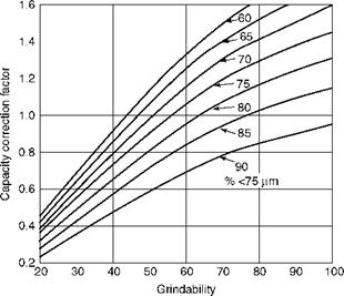
Mill capacity. The output of a coal mill is greatly influenced by the coal properties, namely,
1. Grindability (HGI)
2. Moisture
3. Product fineness
The capacity of the mill varies somewhat directly in proportion to the HGI and inversely to fineness, as shown in Figure 13.15. There are three types of mill capacities as described below. The parameters may differ among manufacturers.
1. Base capacity is at 50 HGI, 70% <75 |jm (through 200 mesh), and 10% inlet fuel moisture.
2. Maximum capacity is derived for the given coal.
3. Actual capacity of the mill is chosen at 85-90% of the maximum capacity to yield a 10-15% margin.
Mill power consumption based on a fineness of 70% through 200 mesh for coal with 50 HGI, is about 7-8 kWh/t.
Mill Construction
Casing. Its purpose is to house all internals and contain the dust-laden air. It consists of the shell, the exhauster, and the rejects hopper and is built as per the recommendations of NFPA 85F to —3.5 atg or 50 psig pressure.
Foundation. The foundation must accommodate three types of forces:
1. Static load of the mill.
2. Dynamic load.
3. Expansion forces on the foundation caused by heating of the mill by the hot PA. This affects the sizing and placement of anchor bolts and concrete reinforcement.
Gearbox
• Mill speeds for big pulverizers vary from 20 to 40 rpm.
• For such low speeds, planetary gearboxes are much lighter and stronger.
• Modern larger mills employ independent planetary gearboxes as opposed to worm and worm wheel-type gearboxes.
• There is no risk of coal powder contamination. The mill shaft is different from the output shaft of the gearbox. Also, there is no large gear in the system.
• The mill outage time is minimized by a spare gearbox unit at the site.
• The gearbox is designed to comply with Antifriction Bearing Manufacturers Association (AFBMA) B-10 life of 100,000 h.
Lubrication system. Modern mills are provided with an external lubrication system to supply cooled and filtered oil to the roller bearings, gears, and thrust pads. The system includes a duplex filter and an oil-water shell and tube exchanger for filtering and cooling the lubricating oil. Starting, running, and stopping functions are interlocked to prevent mill operation without proper lubrication.
Classifier. Situated at the top of the mill, the classifier decelerates the dust-laden air stream and separates the coarse particles. Classifier vanes are adjustable during the mill operation to optimize the fines. The inside of the modern classifier cones is lined with wear-resistant refractory, typically 90% alumina tiles, as a protection from the abrasion of the coarse coal particles.
Mill sealing. Seal air fans are provided to keep the fine dust from leaking from the casing. They are usually designed for 150-200 mm wg above mill inlet air pressure.
Milling Plant Mill sizes
• The nominal diameter of the ring or racer or wheel is the prime dimension in a mill.
• In about six to eight ring sizes of —1750 to 3500 mm (—70 to 140 in.), a range of about 20-100 tph of coal grinding can meet large boiler requirements.
• The diameters of balls and rolls are —20 and 30-35% of the ring diameters, respectively.
• The motor sizes vary from 120 to 650 kW.
• The mill weight, including gearbox, is 60-250 t.
• Mills of 30 and 45 tph nominal capacity are the most common.
Number of mills. Selection of the number of mills involves balancing the requirements of
1. Redundancy
2. Turndown
3. Worst coal analysis
4. Optimum power
The following norms apply. Providing more mills improves the flexibility, but costs more.
• It is best to choose the smallest number of the largest mills.
• The number of mills should meet full boiler capacity with the worst coal.
• This selection usually takes care of the spare mill requirement when normal and design fuels are fired (n + 1 condition).
• Another spare mill may be called for if the normal fuel is less than optimum (n + 2 condition).
• The mill redundancy is very expensive in terms of initial cost.
• The operating costs are also higher, as all the components of the redundant milling train must be maintained.
• Tramp air ingress through the idle burners causes a recurring fuel loss.
Improved coal quality may eventually eliminate the need for spare mills.
Problems in Milling Plant
Wear is the main concern in mills. Wear is a progressive loss of material due to abrasion (sandpapering effect parallel to the surface) or erosion (due to particle impingement at an angle), as elaborated in Sections 3.5.1.2 and 5.8.
In pulverizers, abrasion arises from quartz and pyrite in the incoming coal, particularly for sizes larger than 150 |jm. Although there are established procedures for determining the quantities of these minerals, there is no procedure for deciding the particle sizes. The Yancey, Geer, and Price (YGP) apparatus used for prediction has limited value.
Wear due to erosion is on account of the impingement of air streams laden with coal dust. It is higher at high velocity, particle size, and dust concentration.
Grinding elements are naturally subject to maximum wear. Slow-speed mills are inherently superior for wear resistance.
• Time between the overhauls can be maximized if more wear material can be provided in the grinding area.
• Superior wear-resistant materials can be used.
In areas subject to little or no appreciable wear, the parts should be thinned out to keep the weight and the cost in check. Also, selective lining with hard ceramic materials in specific wear-prone areas greatly improves the availability and life.
High ash content in coal is the main contributor for erosion of mill internals, which is further aggravated by high quartz content. The time and costs of mill maintenance dramatically increase.
Mill fires. Precautions should be included at the design stage. Two types of fires can occur in two different areas of the mill.
1. In the air-inlet chamber, which has the highest air temperature, if the coal dust finds its way to the chamber because of low throat velocity or accumulation soon after a mill trip, fire may occur suddenly.
2. In the cooler part of the mill, which has a high concentration of fuel, a fire can slowly simmer over a long time and under favorable conditions, pick up momentum and destroy a mill.
The mill outlet temperature is the best indication of fire, and any variation should be investigated. It is prudent to follow the NFPA 85 guidelines and install a mill-monitoring system.
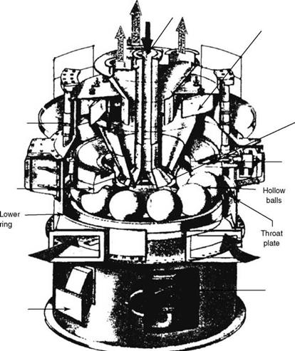
Ball and Racer Mills Licensed from Claudius Peters of Germany, the former Babcock of United Kingdom developed E-mills for coal-fired boilers. These mills have balls instead of rollers (Figure 13.16).
Milling Process. The construction is similar to a ball bearing. About 9-12 balls roll between a fixed top ring and a rotating bottom ring. A vertical drive shaft is rotated in the range of 30-45 rpm by a motor through a gearbox.
The drive shaft is attached to a table on which the bottom ring is bolted. The top ring rests on the balls, and a downward thrust is applied by a hydropneumatic arrangement. A central coal feed chute with a classifier completes the assembly, which is enclosed in a housing.
|
|
|
Loading Cylinder |
|
Upper Ring |
|
Hot primary air inlet |
|
Reject Box |
|
Ground coal + air outlet |
|
Raw coal inlet |
|
Adjustable Classifier Blades |
|
Return of heavy particles |
|
Spider Guide |
|
Gear Box |
Advantages.
1. Ball and racer mills require no lubrication for any internal parts.
2. As the balls wear out, a filler ball is inserted to prolong the running.
3. The fineness of the product increases with time.
Limitations.
1. Although the bottom ring is always separated from the balls by a layer of coal, the top ring stays in contact with the top of the balls and tends to wear faster. Usually, more material is provided in this area in the top ring.
2. After size reduction, the balls have a tendency to ride over the adjacent balls. This makes the mill slightly noisier.
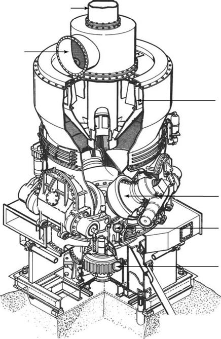
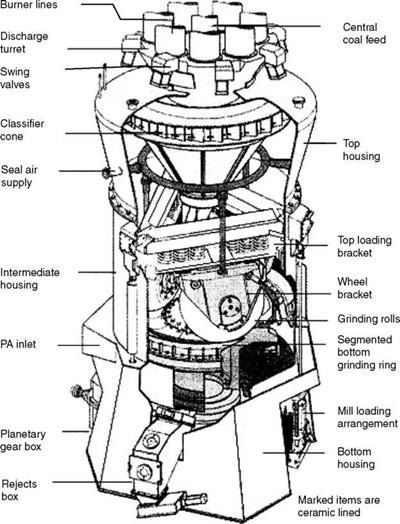
Ring and Roll Mills These include bowl mills (Figure 13.17), MPS mills of Babcock Power, roll wheel mills of B&W (Figure 13.18), and MBF mills of Foster Wheeler (Figure 13.19). In all these mills, there are heavy rollers or tyres, usually three, which trap the coal between themselves and the bottom ring. There are some differences in the way the rings, rollers, and loading systems are built.
The rollers or tyres have the maximum amount of wear material on their outer surfaces. There should be a careful matching of the profiles of the rings and rollers so that the grinding is maximized while the wear is minimum. It is possible to selectively add material at appropriate places in the tyres.
The rings and the rollers have bolted sections with superior wear properties, which can be replaced. Since there are only three huge tyres, these mills should produce lower noise levels because of lower peripheral velocities of the tyres.
Figure 13.17 is adopted from a catalogue of EVT GmbH.
Recent Advances in Vertical PF Mills
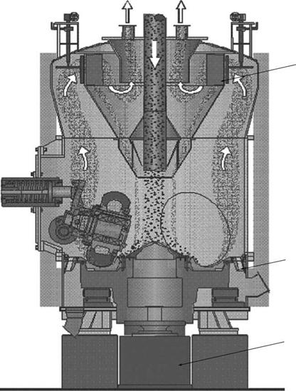
Besides the mechanical improvements, the process improvements are aimed at (1) reducing the auxiliary power, (2) increasing the combustion efficiency, and (3) meeting the emission norms. The enhancements such as improved metallurgy, lining the mill for abrasion resistance with appropriate wear-resistant tiles, introduction of independent planetary gearboxes, and improved mill loading systems have already been mentioned. Rotating throat rings introduced in the 1980s have reduced erosion of throats, enhanced air distribution, and reduced air resistance as well as increased reliability.
Reducing power consumption makes a boiler competitive, as the milling power is a significant part of the auxiliary power. This can be reduced if the weight of the mill is brought down. Makers have reduced the weight by cutting down the material in areas that do not experience wear and selectively increasing the thickness of the wear parts.
Increasing combustion efficiency is possible by improved coal fineness. But this fineness increase consumes more mill power. By using a rotating dynamic classifier the coarse particles on 100 and 52 size mesh are drastically reduced without increasing the fineness of 70% through 200 size mesh using the same power. The unburnt carbon can be as low as 0.5%.
Emission norms. With the reduction in coarse particles, the fuel burns more evenly without excessive flame temperature, which contributes to the lowering of NOx generation.
|
|
|
Raw coal inlet |
|
Ground coal + air outlet |
|
Hot Air Inlet |
|
Classifier |
|
Grinding Rollers |
|
Grinding Bowl |
|
Gear |
|
RvvT: |
|
FIGURE 13.17 Exploded view of a typical bowl mill. |
|
FIGURE 13.18 Roll wheel pulverizer showing integral ceramic lining. (From Babcock and Wilcox Company, U. S.A. With permission.) |
Coal pipes carry a PF-PA mixture from the mill to burners along with the moisture of the incoming coal that is heated and dried before grinding. Primary air is constant at —1.75 kg/kg of coal at full load, whereas the moisture varies.
• Coal pipes are usually made of 12 mm medium-carbon steel (CS) pipes.
• Cast basalt is usually provided for lining of bends. With abrasive coals, the lining may be of hard ceramic material.
• Coal-air velocities are very carefully chosen to balance erosion and settling of coal powder in horizontal runs. This velocity decides the pipe sizes and the mill turndown.
|
|
|
Rotating or Dynamic Classifier |
|
Rotating throat ring |
|
Removable planetary gear box |
|
FIGURE 13.19 MBF mill with rotating classifier and throat ring. (From Foster Wheeler Corporation, U. S.A. With permission.) |
• For settlement of ground coal, 15 m/s (50 ft/s) is the minimum velocity. To minimize erosion, the maximum velocity is 33 m/s (110 ft/s) for soft coals and 25 m/s (82 ft/s) for abrasive coals, for coal fineness of 70% through 75 |jm mesh.
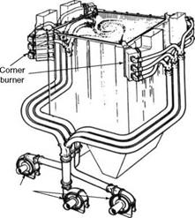
• Coal pipes should be of equal lengths to avoid unequal flow between burners. Typical routings for front-wall-fired and corner-fired boilers are shown in Figures 13.20 and 13.21, respectively. Balancing orifices may be needed to equalize the flow.
• Isolating valves at the mill and burner ends and diverters and splitters in the pipes are subject to heavy wear. A good understanding of the wear of the fittings is necessary to make a proper selection.
|
L |
|
1 |
|
0 Burners |
|
Fl rl |
|
L |
|
4 |
|
V V |
|
2 Mills 3 |
|
//////// |
|
T7/777TT“ //////// //////// |
 |
|
|
|
|
|
|
|
![]()


 13 сентября, 2013
  admin
admin 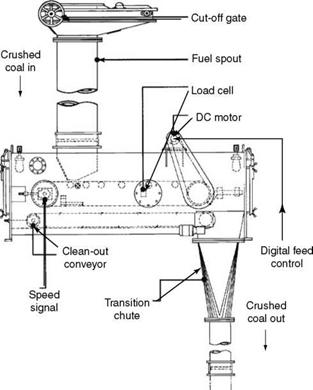
 Опубликовано в рубрике