Oil and gas are clean and quick-burning fuels that require smaller furnaces and lesser HS in the tube banks. The boilers are compact. This feature enables shop manufacturing of
|
[LST- |
|
Atomizing steam valve Air Register ///// 1———— |
|
Flame detector Main burner gun (with insert retract cylinder) I Cylinder and fuel oil valve |
|
Pilot Burner Flame detector Pilot gun and fuel gas valve Igniter (with igniter transformer) Main oil burner |
|
|
 |
|
|
|
 |
|
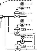

FIGURE 10.33
Typical simplified burner management and safety system scheme for oil burner.
The boilers and assemblies for modular boilers that require minimum erection time. NG — fired boilers tend to be the most compact because of very small furnaces and convection banks. This is due to very high heat release in the furnace and very high gas velocities in convection banks. As the fuel becomes dirtier, the boilers require more capacity or yield less output.
Package boilers are mainly of three types—O, A, and D, named for their shapes. The advantages of package boilers are as follows:
1. Better fit and finish due to shop assembly.
2. Reduced delivery time and costs.
3. Site work reduced to a minimum.
4. No site-storage space required, as the boiler can be placed directly in its final location. Hence, a congested site is also acceptable.
The transportation cost, however, is quite high. On the whole, the overall installation cost is usually lower and hence the package boilers are very popular. Since they are
Standardized, the manufacturers can batch-produce them and sell them with short lead times. The package boilers are characterized by the following features:
• The gases traverse from front to rear and back again to the front.
• The gas flows are horizontal.
• The back-end equipment, namely, the economizer (ECON) and the airheater (AH), are located alongside the boiler.
• The ECON and AH are both shop-assembled.
• The boilers are usually bottom-supported.
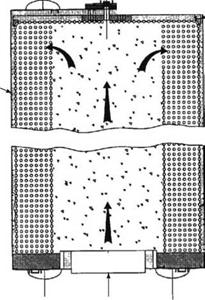
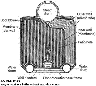
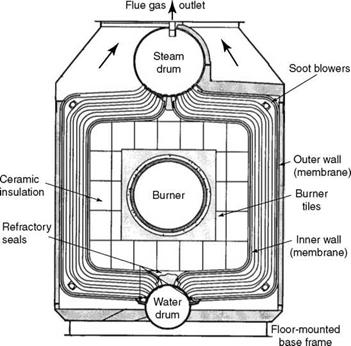
The classical bidrum boiler bank (BB), with about 20 tubes, is split in the middle to create a furnace chamber. In the O-type design, the two sets of tubes join the bottom drum, whereas in the A-type, there are two bottom drums far apart. Both designs are symmetrical about the centerline and are perfectly balanced, making the transport easy (Figures 10.34 and 10.35).
|
Drum Peep C/L hole |
![]()
|
, Access Drum ^ door |
![]()
|
Door C/L |
![]()
|
Burner Throat |
![]()
|
I».,, |
![]()
|
FIGURE 10.34 A-type package boiler—front and plan views. |
 In the O-type design, the furnace space is very small and hence the boilers are limited to —35 tph capacity. Both designs are compact and can be good solutions where space is a constraint. Foundation requirements are minimal with only a concrete floor required for the boiler.
|
FIGURE 10.35 O-type boiler—view from inside toward front. |
|
TABLE 10.6 Approximate Range of O — and A-Type Boilers
|
Small furnaces make them more suitable for high-CV oils and gases with low residence times. The fuels are required to be clean because the horizontal gas flow pattern precipitates the dust, which would otherwise choke the tube passages over time. In both the designs, accessibility is limited. Superheater outlet temperature (SOT) is also limited.
The A-type boilers have a much bigger range of capacity. The steaming range for both designs is depicted in Table 10.6.
Much larger boilers can be built with D-type designs. The entire boiler is usually shipped as a single unit, as shown in Figure 10.36, but very large units are shipped in two pieces— the drums and the C panel of the furnace.
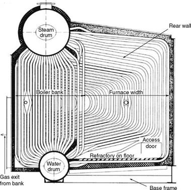
While a bidrum bank is split in the middle for O-type or A-type boilers, in D-type boilers, the end tube is pulled out to accommodate the furnace (Figures 10.37 and 10.38).
|
FIGURE 10.36 Transportation of package boiler. |
|
FIGURE 10.37 Cross-sectional elevation view of D-type package boiler (view from burner side). |
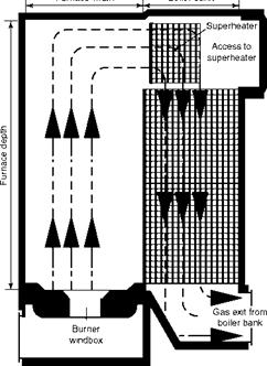
The burners are located on one end and the gases travel longitudinally along the axes of the drums. Due to the horizontal travel of the gases, this design is better suited for cleaner fuels that do not precipitate dust or sludge, which can pack up the tube banks. These boilers are designated FM, VP, and supercritical (SC) boilers by the Babcock, Alstom, and Foster Wheeler groups, respectively. Most leading boiler companies have their equivalent designs.
The boilers are bottom-supported with forced-draft natural circulation and fully water — cooled with minimum refractory; they also have fully drainable SHs and outdoor-type boilers capable of burning all liquid and gaseous fuels, including lean fuels such as blast furnace gases and biogases. Single-burner designs have auxiliary atomizers that can be brought on range to take out the main gun for maintenance without any boiler stoppage.
|
Furnace width
|
FIGURE 10.38
Plan view of D-type boiler showing gas flow.
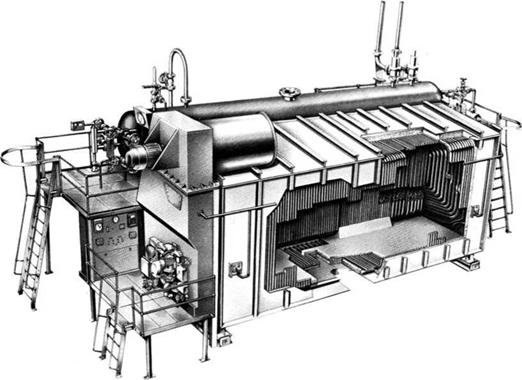
All the auxiliaries are positioned in a compact manner. There is no requirement of foundation other than a flat concrete floor. Figure 10.39 shows a typical small D-type boiler.
Each company has extensively standardized its D-type boilers. Although they produce lower evaporation compared to the field-erected units, the package boilers are the most highly rated boilers, as they are compact and easily transportable. Further, since they are used mostly with oil and gas, which are fast burning and clean, their heat release and absorption rates tend to be the highest.
Design aspects of D-type boilers. The following design aspects of D-type boilers are applicable to all the package boiler designs.
Boiler
• The evaporation values given in Table 10.7 are based on generating saturated steam.
• In the smallest size boiler, the minimum flame length decides the furnace depth, which is —2.5 m. The furnace depth is the dimension along the drum length.
• For smaller boilers with shorter furnaces, circular register-type burners with short flames are used. However, for larger boilers with longer furnaces, parallel-flow burners with low excess air and longer flame lengths are employed.
• Boiler lengths can reach —9.5 m with about 100 tube rows in the boiler bank. This is limited by the permissible furnace pressure.
• The dividing wall between the furnace and the bank has to be sealed perfectly to prevent gas bypass, leading to a loss of performance. As the pressure difference increases, the tendency to bypass also increases.
|
FIGURE 10.39 Small single-burner D-type package boiler with fan mounted on top and local control panel. |
|
TABLE 10.7 Approximate Range of D-Type Boilers
|
Furnace
• The furnace is highly rated with a
O Volumetric heat release of maximum 1.45 MW/m3 (—1,246,000 kcal/m3 or —140,000 Btu/ft3).
O Heat flux of up to 0.63 MW/m2 (—542,400 kcal/m2/h or —200,000 Btu/ft2/h), which is high enough to require complete water cooling with minimum refractory.
• This high-heat loading helps to maintain thermosymphonic head, even with very short drum centers.
• The furnace exit-gas temperature (FEGT) is limited to 1400°C (~2550°F) to prevent fouling and overheating of the SH.
• The furnace floor is covered with refractory tiles to prevent steam formation that can lead to tube overhe ating.
• The furnace enclosure is fully welded to prevent gas leakages and also rigid enough to withstand the lifting forces.
• The furnace pressure in pressurized units can be as high as —800 mbar (~600 mm wg or —24 in. wg).
Boiler bank
• The minimum drum center distance is 2.75 m (—9 ft) based on circulation considerations.
• The BB exit-gas temperature (BEGT) is limited to —450°C (—850°F) to avoid inside insulation of the exit duct and to prevent reverse circulation of water in the final tubes.
• A drawback in the D-type boiler design is the lack of accessibility into the BB made worse by the presence of a rotary soot blower (SB). In some designs, this is remedied by avoiding a few bank tubes to provide access. Short soot blowers are inserted in that access space from the sides for a better cleaning instead of a long rotary blower. This must be done with care to avoid hot spots on the exposed parts of the drums, as they are no longer cooled after the removal of bank tubes.
• In any package boiler, the drums are long and the circulating water flows along the axes of the drums. The front rows of the BB, about one-third of them, act as downcomers. At the rear end, where the SH is located, there are no risers and the gases are at their hottest. A few risers beside the end row have to be judiciously placed to provide sufficient axial flow of drum water to prevent any overheating of the drums.
• The BB tubes can be in-line or staggered for clean and fouling fuels, respectively. Usually, the number of bank tubes is 10, instead of —20 in a normal bidrum arrangment.
• The gas velocities can be as high as 30 m/s (—100 ft/s) in convection banks with clean fuels. Tubes are usually swaged to improve the ligament efficiency and reduce drum thickness. Loading on drum internals tends to be very uneven, as the front one-third of the tube bank is made of the downcomers and the first few tubes at the rear side generate heavy amounts of steam. It is therefore customary to fill the entire drum length with internals.
SH
• The SH is usually drainable along a single loop of an inverted U. As the required superheat increases or a larger control range is desired, a double inverted U-type SH may have to be adopted, making the heater nondrainable. The SH in a package boiler is largely convective.
• The degree of control range is also not as large as in field-erected boilers. Occasionally, a loop is pushed into the furnace space to achieve higher temperature.
Fuels and burners
• One- to four-burner configurations are possible in a D-type design, whereas in A- and O-types, only one or two burners are used.
• Besides a range of oils and gases, the package boilers can also burn low-CV waste gases such as BFG and CO.
• With waste fuels having dust in the gas, it is desirable to have o Additional soot blowers
O Extra wash-water drains at the bottom of the boiler
O A few lance ports in the boiler sidewall for hand-lancing the deposits in the BB
The low-CV waste gases are slow-burning and voluminous. The volumetric release rates have to be lowered. For CO gas, the rate is 0.41 MW/m2 (—356,000 kcal/m3/h or —40,000 Btu/ft3/h), and for boiler feed (BF) gas, it is 0.20 MW/m2 or (—178,000 kcal/m3/h or —20,000 Btu/ft3/h).
• In addition, the fully water-cooled furnaces of the package boilers tend to overcool the already low-temperature flames of the waste gases, making it difficult to sustain combustion. Hence, a certain amount of supplementary fuel such as FO or NG has to be burnt in a pilot burner to maintain the flame temperature high enough for sustained combustion. Also, the front portion of the furnace has to be lined with refractory to retain and reflect the heat to reduce the auxiliary fuel support.
• Gas spuds cannot be used for these voluminous gases. Scroll burners, such as the one illustrated in Figure 10.17, are used for BF gas, whereas a central pipe in the burner carries the CO gas. Since these gases contain a lot of CO, the furnace is operated in a balanced draft mode with an induced draft (ID) fan.
• For larger gas quantities, the package boilers become unsuitable. The draft losses are also excessive. Field-erected boilers are better suited.
Field-erected modular boilers are well suited for:
• Larger capacities than the package boilers for process or power
• Burning fuels with more dust or sludge that require better access for maintenance
• Slow-burning and lean fuels such as CO or BF gas that require a generous furnace and convection bank
The field-erected modular boilers are bottom-supported, fully membrane panel, water — cooled, and outdoor boilers with large SHs; they are capable of burning most liquid and gaseous fuels. These are designated as PFI/PFT, VU60, and SD boilers by B&W, Alstom, and Foster Wheeler groups, respectively.
The range covered by the bidrum and single-drum boilers is given in Table 10.8. The single-drum boilers can be built for slightly higher capacities, pressures, and temperatures.
|
TABLE 10.8 Steaming Ranges of Field-Erected Modular Boilers
|
There is no decided advantage of one over the other. The single-drum boilers are normally European, whereas the bidrum boilers are American preferences. The single-drum boilers are also extensively standardized, and modular manufacturing is adopted to shorten delivery, reduce costs, and improve quality.
• The heat ratings of field-erected boilers are a good deal lower than those of the package boilers. Maximum heat release rate is limited to 0.58 MW/m3 (—500,000 kcal/m3 or 56,000 Btu/ft3) as opposed to 1.45 MW/m3 in package boilers. Likewise, the heat flux, FEGT, and gas velocities are all lower.
• Unlike in package boilers where the flue gas flow is horizontal, in field — erected boilers, flow is normally up and down, facilitating the separation of dust from gas.
• These boilers can be front-fired or corner-fired. In front-firing, there are either two or four burners. The furnace has generous proportions to accept low excess-air, parallel-flow burners or slow-burning low-CV gases, requiring large volume or liquid fuels that contain sludge or alkali compounds.
• The floor is covered with tiles to protect the tubes from overheating.
• The SH is suspended from the roof and expands freely downward. Usually, it is a nondrainable SH. For small superheating, drainable SHs can be accommodated. The SH is protected from direct radiation of burner flames by the furnace arch but receives furnace radiation indirectly.
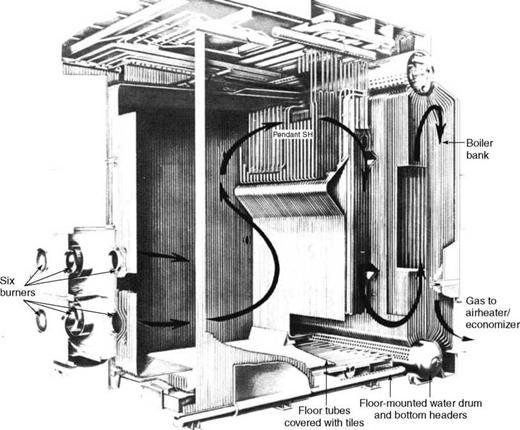
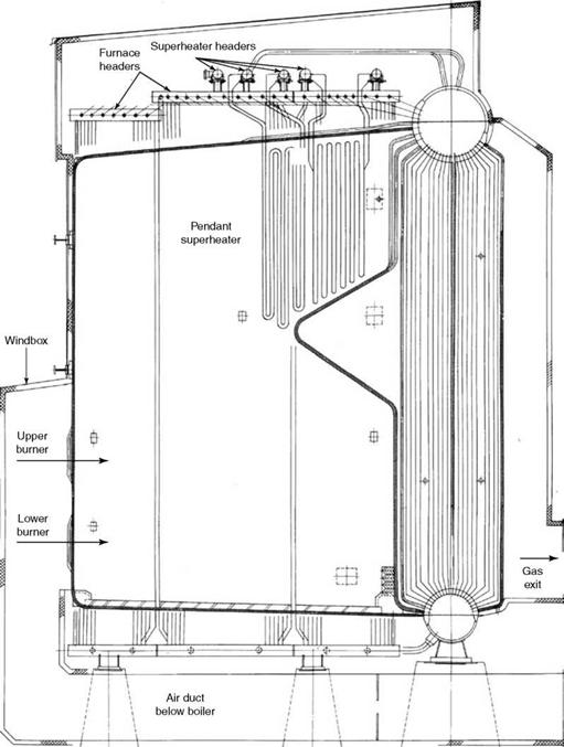
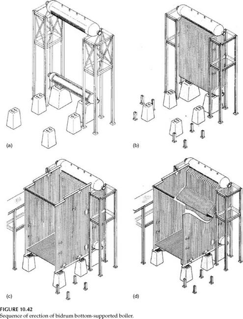
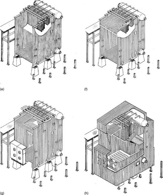
• The BB is tall with about 20 tubes along the drum circumference. The tubes are usually placed in line, and the gas flow can be longitudinal or cross flow. The rear third are downcomers. At times, unheated downcomers are used to improve circulation (Figures 10.40 through 10.42).
• Steam requirements fall outside the bidrum package or field-erected boiler capabilities.
• Higher pressure or temperatures are required in cogen systems such as fertilizer plants and refineries.
• Superior dynamics are desired as in power or cogen applications.
• For pressures up to 60 bar, an evaporator (EVAP) coil is required because the saturated heat to be absorbed is considerable.
|
FIGURE 10.40 Bottom-supported, field-erected modular boiler with front firing. (From Foster Wheeler Corporation, U. S.A. With permission.) |
• Up to —30 kg/cm2, the EVAP may additionally require a circulating pump to draw saturated water from the drum and push it through the coil to ensure circulation under all loads.
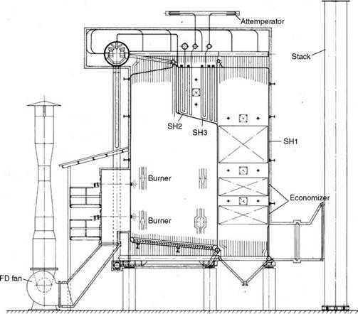
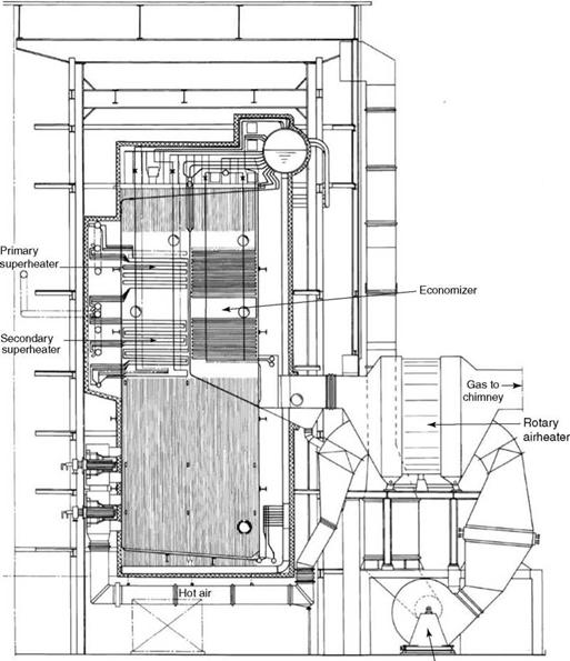
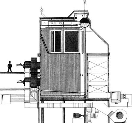
• The single-drum boilers are of two passes (Figure 10.43) or one and a half pass (Figure 10.44) or special designs (Figure 10.45), depending on the final temperature, control range requirements, and the fuel.
• The water-holding capacity is smaller in comparison with bidrums. Also, the tubes are smaller and thinner, thereby reducing the thermal inertia and improving load response.
• The SHs are fully or partly drainable.
• The burners are usually in the front wall, but floor and roof burners are also common.
• Front-wall firing takes more floor space than bottom-fired boilers. The latter are taller but their burners are accessible from the floor. In bottom-fired
|
FIGURE 10.41 Cross-sectional view of two-pass bottom-supported boiler. (From Foster Wheeler Corporation, U. S.A. With permission.) |
|
|
|
FIGURE 10.42 (Continued) |
|
FIGURE 10.43 Two-pass boilers with partly drainable superheater and front firing with pressurized furnaces. |
Boilers, temperatures only up to 500°C can be obtained, as a pendant SH cannot be accommodated.
• In all designs in the second pass, it is normally possible to accommodate an ECON bank below the SH, resulting in a compact arrangement.
• A one and a half pass boiler with front-wall firing is a proven design combining drainable surfaces and high superheat temperature. The SH receives radiation from the burner flames and displays a fairly flat characteristic with load. An ECON bank can be accommodated in the boiler setting (Figure 10.44).
• The two-pass front-wall firing design provides a generous furnace volume and a second pass for the SH and the ECON, which are fully drainable. When steam temperatures higher than ~520°C are desired or a larger turndown is required, a nondrainable pendant SH can be added in the furnace (Figure 10.43).
For light oils and gases, the design shown in Figure 10.45 is fully drainable and very compact. It covers a range of 25-200 tph.
|
FD fan FIGURE 10.44 One and a half-pass boiler with front firing and drainable horizontal superheater. |
|
FIGURE 10.45 A compact single-drum boiler with drainable superheater. |
Further Readings
Bryant, J., 1980, Update your flame monitoring know-how, Power, August.
Combustion Fossil Power, Combustion Engineering.
Delacy, J., 1990, Auxiliary burners can wield system performance, Power, June.
Hutchins, J. L., 1969, Design of large package boilers in light of operating experience, Combustion Engineering Inc., TAPPI, Combustion, March.
Lohoff, K. and Oppenberg, R. Combustion of liquid and gaseous fuels; Stages of the ASR burner development for NOX reduction, Deutsche Babcock.
McKenzie, E. C. Design and development of multi-fuel burners.
Mockeridge, E. H., 1974, Utilization of package boilers for the combustion of waste fuels, B&W Inc., USA, American Power Conference, May.
Niepenberg, H. P. Development of burner technology for liquid and gaseous fuels from the beginning of the seventies to the nineties, Deutsche Babcock.
Steam, Its Generation and Use, Babcock and Wilcox Company.


 4 сентября, 2013
  admin
admin 

 Опубликовано в рубрике