Pulverized firing burners are mounted on the furnace where the PF, PA, and SA come together to get properly mixed and enter combustion. Combustion of the pulverized coal particle starts with immediate flash drying of moisture and devolatilization due to the combination of intense radiation from the flame and convection from the hot gases.
• The combustion of volatiles takes —0.1 s and adds to the heat of the flame and provides heat for ignition as well as combustion of char (the devolatilized FC). Unless VM is in adequate amounts of —20% on a daf basis, proper ignition cannot be assured.
• The char takes between 1 and 2 s to reach ignition and burn out. For the completion of combustion reactions, (1) the furnace temperature should be sufficiently high and (2) the volume should be adequately large to provide this residence time. Coarse particles larger than 100 |jm take longer time to burn out due to higher surface-to-mass ratio.
• Secondary air has to scrub the coal particle to remove the ash layer on the surface and expose fresh coal for burning. The higher velocity of the SA in the tangential firing or rotary motion in circular burners performs this scrubbing action.
• In case of high-ash coals, this scrubbing is even more important, as carbon is trapped within the thick-coat ash particles. Higher carbon loss appears unavoidable.
• The fuel moisture evaporated and transferred to the PA by milling extracts heat from the furnace first to get superheated and dissociated at a high temperature. Thus the fuel moisture has a quenching action and is actually a retardant to the combustion process.
• At more than 40% fuel moisture the normal PF mode of combustion cannot be sustained with coal.
• The brown coals with as high as 70% moisture can be burnt only because of the high volatiles. They require a much higher temperature of flue gas for drying and
A longer residence time for combustion, which accounts for the need for employing corner firing.
Performance requirements of burners. Pulverized firing burners should meet the following requirements as a minimum:
• They should operate reliably with steady flames with no flickering without the need for stabilizing oil or gas support, preferably from 30% load upward. This requirement is dependent on the mill, furnace, and coal pipe sizing as well.
• They should operate with the least carbon loss and minimum acceptable CO and NOx emissions. CO and NOx work in opposite ways. Low NOx gives high CO due to low air and low temperature, and vice versa.
• Stainless steel (ss) construction for heated parts should minimize maintenance.
• Safety is paramount. A good-quality burner management system (BMS) with proven logic and robust components is vital.
All PF systems require (1) light-up burners to ignite the coal flame and (2) load-carrying burners to build up the load until the coal firing occurs. The fuel system in a PF boiler is thus very elaborate.
• The main fuel needs include:
— Fuel gas for igniters
— Oil for lighting up the main fuel or carrying low loads
— Main fuel oil support for load carrying and main burner stabilization In addition, steam or compressed air is required for atomization.
• Light-up burners are usually oil burners using light oils. Since the large PF furnaces are cold initially, only light oils should be used for cold startups. With heavy oils there are chances of formation of pools of unburnt fuel, resulting from the chilling of flames in a cold furnace. When these unburnt oil patches get agitated with hot gases as the boiler warms up, they catch fire and can cause severe explosions. The light-up oil burners are usually sized for —10% of the boiler duty to enable steam generation in the boiler to provide atomizing steam to load-carrying guns.
• Load-carrying burners may use heavy oils. They light-up burners and build up the load. The load-carrying burners follow are designed for a minimum heat equivalent of the output of a single mill, so that the furnace does not experience a big thermal shock when the mill is cut in. They can, of course, be sized for full duty of the boiler if required.
• Load-carrying burners support the main coal flames at low loads so that they do not flicker. The flickering can occur at low loads when the flame is unstable. The flame extinguishes and reestablishes in which interval a certain amount of fuel escapes unburnt, to explode later. Whenever a mill operates at less than about half of its capacity, load guns are pressed into service.
• Light-up burners are normally pressure or mechanically atomized due to lack of steam at the start of the plant. Alternately, plant air can be used for atomization. However, if steam can be made available for startup, the light-up burners can be steam atomized as well.
• Load-carrying burners are mostly steam atomized.
• The same atomizer can be designed to perform light-up and load-carrying duties.
• A light oil pumping and straining unit upstream of the boiler is required to provide oil for light-up at room temperature. A P&H unit for providing heavy oil at the right pressure and temperature is also needed for load-carrying duties.
Igniters or light-up burners must be started with the help of another fuel, which is normally gas that must be ignited by electrical energy. Gas-electric (GE) igniters are common due to their simplicity, reliability, and cost, although another fuel is introduced into the system. Refer to Section 10.2.9 for more details on igniters.
13.4.1 Flame Monitors and Burner Management System
Any burner must be protected from loss of flame by a suitable flame detector. In a PF burner it is normal to have detectors for igniter, light-up, and load-carrying oil or gas flames and the main flames. The flame monitors are integrated into the BMS, which provides for safe startup and shutdown of burners. Unless safe conditions are detected and confirmed, logic does not permit furnace purge, which is followed by light-up in a certain sequence. Likewise, the shutdown requires a safe withdrawal of burners from operation. Guidelines in the NFPA recommendations are periodically amended to incorporate recent experiences. The basics of BMS for oil or gas are briefly described in Section 10.2.4.
Four types of burners cover all ranks of coals:
1. Wall-mounted horizontal circular burners for normal bituminous and sub — bituminous coals
2. Corner-mounted horizontal tangential burners for normal bituminous and sub — bituminous coals
3. Roof-mounted vertical down-shot burners for low-volatile coals, anthracites, cokes, etc.
4. Corner-fired burners for brown coals and peat with high moisture
Circular and tangential burners for normal bituminous coals are the most common ones.
In a circular burner shown in Figure 13.22, the PF-PA mixture enters the furnace through a central pipe, whereas SA from the windbox is admitted tangentially to give a swirl to the gases. Primary air and secondary air are nearly at right angles to each other so that the fuel particles are scrubbed effectively. The flames are short, bushy, and turbulent. NOx formation is high, and the modern designs adopt splitting of SA to prolong the combustion. Further, sharing of air around the main combustion zone produces more staged combustion, resulting lower NOx. A compartmented windbox with independently measured airflow is one of the first ways to reduce NOx.
|
|
|
Register |
|
Air-rich |
FIGURE 13.22
Circular burner.
• Circular burners are built for heat duties from —15 to 90 MWth or —12 to 75 mkcal/h (—50 to 300 MBtu/h).
• They can be placed in one wall or opposite walls for front-wall or opposed-wall firing.
• Coal pipe routing is simpler and cheaper, but the furnace is taller and rectangular in single-wall firing.
• Cost and practice decide the type of wall firing. Normally, for 200 MWe and above, opposed wall firing is employed.
• Bituminous and sub-bituminous coals and lignites with <40% moisture can be fired in the circular burners.
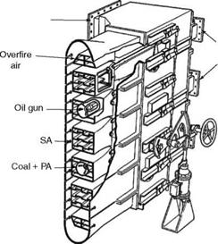
There is no swirling of air in the tangential burners (Figure 13.23). The PA and the SA introduced into the furnace through burners in several small alternate streams travel parallel with no appreciable intermixing. From the four corners of the furnace, the streams travel toward an imaginary circle in the center where a turbulent swirling takes place and combustion is completed as shown in Figure 10.23. Gases make use of the entire furnace to generate a cyclonic motion, thereby providing the necessary scrubbing.
• The burning is relatively slow and even. There are no hot spots.
• During the travel from the burners to the fireball, the coal devolatilizes and partly burns in an air-deficient atmosphere, as the streams do not intermix. This results in a reduction of nearly 50% of NOX as compared to wall firing.
• A further reduction is obtained when —20% of total air is provided as OFA at the tops of the burners. This results in stoichiometric conditions in the fireball with no spare oxygen for NOX formation.
The burner capabilities are similar to those of the circular burners; tangential burners are suitable for a wide range of normal coals, but at both ends of the scale, there are limitations of combusting very low-volatile high-rank coals or high-moisture low-rank
|
|
|
Windbox |
|
SA dampers |
|
Tilting mechanism |
|
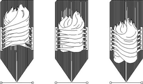
FIGURE 13.24 Flameball in furnace in upper, middle, and lower positions. |
|
FIGURE 13.23 Tangential burners with secondary air for low NOx. |
![]() Coals. However, because of their long travel and residence time, the tangential burners can handle low-volatile coals better than the circular burners. For very low VM, however, the down-shot burners are the only solution.
Coals. However, because of their long travel and residence time, the tangential burners can handle low-volatile coals better than the circular burners. For very low VM, however, the down-shot burners are the only solution.
As these burners use the entire furnace to develop the flames and the fireball, it is possible to move the ball upward or downward to shift the center of heat input to minimize attemperation and compensate for the effects of ash deposits. This is shown in Figure 13.24. A similar provision is available in the wall firing by cutting the top and bottom rows of burners in and out.
|
TABLE 13.3 Comparison of Circular and Tangential Burners
|
Circular versus Tangential Burners
For most applications, boilermakers offer two designs, depending on their standards. The burning philosophy, arrangement, and effects on the furnace and SH, and attemperator system differ but exhibit no difference in efficiency and performance. Table 13.3 compares these two systems.
Down-shot burners, with their long flames, are essentially for low-volatile coals. There are two areas of applications. In both cases, the combustion is slow and the furnace volume required is large. Residence time is typically as high as 3 s.
1. Very low-volatile coals, such as anthracites with dry ash-free (daf) volatile content of 9-13%, do not burn in normal burners, as there are not enough volatiles to raise the flame temperature to the high ignition levels required. Besides, the combustion is very slow, requiring a hot and big furnace.
2. High-ash coals with low volatiles (<20% on daf basis) produce flame instability at low loads, calling for an extended oil or gas support.
Difficult fuels are burnt in down-shot burners. In fact, these burners, also called vertical or arch-mounted burners, were early examples of PF firing.
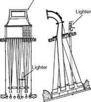
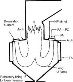
In down-shot burners, PA and coal are admitted in a downward pattern, with SA also alongside. The burners are mounted on the front and rear arches of the boiler. The flames travel in a U-pattern and join in the central shaft of the furnace. The refractory-lined sloped furnace bottom guides the flame. The refractory inhibits the heat absorption and radiates it back to the flame so that the combustion of char is maximized in the very hot environment. The tertiary air (TA) is provided near the slopes to achieve staged combustion. Fineness is required for good combustion of char.
The burners are actually small jets introduced between the roof tubes. There is no swirling. The ignition takes place due to the radiation of the furnace heat. The good carbon burnout, at best 95%, is due to the
• Long residence time of the flame (3 s)
• Finer grinding (100% through 200 mesh)
• High mill outlet temperature (~100°C)
• Reduction of heat from the furnace refractory
|
FIGURE 13.25 W-type down-shot firing. |
![]()
|
PA + PC PA + PC |
![]()
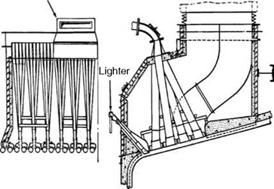 Furnaces can fire from one side in a U-pattern as shown in Figure 9.25 or from both sides in a W-pattern as shown in Figure 13.25, depending on the boiler size. In Figure 13.26,
|
|
Two types of burners are shown for nonabrasive and abrasive coals. The abrasive coal is admitted between the tubes.
The burner stability is outstanding, and the savings on support fuel are high. The installed costs and space requirements of the down-shot boiler are significantly more, and unless the main fuel costs are low or the oil or gas costs are high, this arrangement cannot be justified for normal coals. For anthracites and pet cokes, the flame temperatures due to the burning of char are so high that the NO, limits are not met in many locations.
This method is developed for firing high-moisture fuels such as brown coals and peat. For firing of brown coals with up to 70% moisture, very high-temperature gas from the furnace, >1000°C, is necessary for fuel drying, and even then the fuel enters the furnace with —20% moisture. Getting hot air to such temperature is not possible. Flue gas is better for drying and conveying because its high oxygen content is highly reactive and prone to spontaneous combustion if air is used instead.
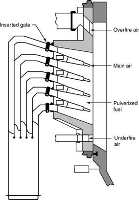
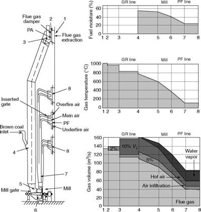
The fuel sizing need not be fine: 60% through 200 mesh is adequate. This is because the radiant heat causes an instant flash drying of fuel on entering the furnace, leading to an explosive expansion of water vapor, resulting in the breakup of coarse fuel to fines. The volatiles get released from the freshly created surfaces and burn instantly to provide more heat than that consumed by evaporation of fuel moisture. This excess heat sustains the combustion. The resulting furnace temperature is lower, calling for a slightly longer residence time and turbulence. Firing from corners and creating a cyclone similar to that obtained in tangential firing provides the necessary time and turbulence. Figure 13.27 shows the burner arrangement. A burner-tilting arrangement for steam temperature control is not possible here, due to the burner size constraint. The NO, is also not very relevant, as the firing temperatures are never high enough due to high fuel moisture. Figure 13.28 shows the temperature profiles and fuel moisture variation in a typical corner firing of brown coal with 55% moisture. The carbon burn-up efficiency can be as low as 0.05% for brown coals.
Low NO, combustion started from the early 1970s. See Section 10.2.8 on low NO, burners and Section 12.2.3 on denitrification. Conventional circular burners produce maximum heat per unit volume and, in the process, generate high NOX of —1000 to 2000 mg/N/m3 (—500 to 1000 ppm), whereas the tangential burners produce about half of this amount. Low NOX burners can achieve —200-600 mg/N/m3 (100-300 ppm).
Coals typically contain small amounts of N2, ranging from 0.5 to 2%. In PF firing, 75% of the NO, formed is fuel NO, and the rest is thermal. Fuel-bound N2 reacts with excess air at high temperature created by the oxidation of char and forms NO,. Coals with high VM are NO, friendly, as they burn faster but at a lower temperature. Fixed carbon in coal acts in the opposite manner and creates peak flame temperatures. The FC/VM ratio indicates the tendency of NOX formation—the higher the FC/VM ratio, the greater the NOX generation.
Thermal NOX forms at temperatures >1538°C (2800°F). To reduce NOX, low-NOX burners, with tangential entry of air replaced with axial flow, are required.
1. Minimize the free O2 available by minimizing excess air to the burner. This method involves only a careful measurement and distribution of air. This will
|
FIGURE 13.27 Burner for corner firing of brown coal. (From Babcock and Wilcox Company, U. S.A. With permission.) |
Also inhibit the formation of thermal NOx by making free oxygen scarce. About 10-15% of NOx can be reduced this way.
2. Lengthen the combustion to lower the flame temperature, which retards the reaction by staging the combustion. This is effective for thermal NOx inhibition.
3. Provide less air at the beginning to create a sub-stoichiometric condition in which C and CO are present, which reduce the NOx to elemental N and thereby reduce the fuel NOx level. This is the most effective method in which —40% reduction of NOx is possible.
The combination of these three actions reduces the NOx formation. To minimize the excess air to really low levels, gas recirculation (GR) is used. The fluid mass is maintained for providing a good turbulence, but the air is replaced by the flue gas that has no free O2 to react with N2.
Another popular measure is to reduce the fineness of coal and coarse sizing through the 52 mesh so that the combustion uniform without hot spots responsible for NOx production. The carbon burnup is also better.
|
Sampling points FIGURE 13.28 Typical fuel and air property changes in corner firing. (From Babcock and Wilcox Company, U. S.A. With permission.) |


 13 сентября, 2013
  admin
admin 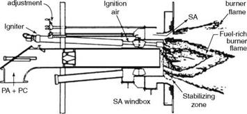
 Опубликовано в рубрике