Chapter 6 discusses more details.
No boiler is designed from the first step. The previous experiences of the customer, the consultant, and the contractors are required to evolve a new design by modifying a successful model of the nearest size. The fuel characteristics play the most important role. The technical specifications of the client usually capture such details.
Furnace
Sizing of furnace has the highest influence on the cost and performance of the boiler. Unlike tube banks, the furnace cannot be altered after its construction. Feedback on the existing units with similar fuels provides more reliable design data when a new unit is planned than any amount of calculation.
With high heat inputs of the modern burners, the furnaces must be fully water cooled with a minimum amount of refractory. Membrane panels have now superceded tube and
Tile or tangent tube construction. Membrane bars have to be restricted to 19 mm (3/4 in.) width and should be of 8 mm thickness to withstand the high fluxes of the burner zone.
• Ribbed or rifle tubes are sometimes provided in the high-heat burner zone around the burners when high heat flux may overheat the tube due to departure from nucleate boiling (DNB).
• The furnace plan area must be adequate for full development of flames. Heat release in the plan area is around 3.15 MW/m2 or 2.7 X 10⁶ kcal/m2/h (1 X 10⁶ Btu/ ft2/h) to meet low-NOX conditions, decreasing by —30-50%.
• The furnace height from the center of the heat input (with upper burners) to the middle of the furnace exit plane should give a residence time at full load exceeding the minimum residence time requirement of —1-2 s (depending on the coal properties). The residence time depends on the FC/VM ratio and is best derived from the existing operating data. This would translate to a furnace volumetric heat release rate of —0.1-0.16 MW/m3 or —90,000-1,350,000 kcal/m3/h (—10,00015,000 Btu/ft3/h) for slow and quick burning of coals, respectively.
• The heat flux in the area around burners is more important than the overall furnace heat flux, as this zone is susceptible to DNB particularly in wall-fired boilers.
• The distance from the top set of burners to the tip of nose or the edge of platen is another important dimension to monitor to prevent overheating.
• Since coal is pulverized and fired and the flame temperatures are high, the slagging of ash is to be expected. Wall blowers or wall deslaggers are essential.
• As the boiler grows in size, the furnace volume increases more than the area, leading to a mismatch, and more HS is needed. To maintain area to volume in a proper manner, division walls in furnace are provided. Wing wall and platen SHs also help to meet this need.
• For utility applications, platen SHs are almost always provided in the furnace. Spaced at 600-1000 mm (—2-3 ft) apart, depending on the slagging history of the coal, platens are used for heating steam at the lower end of the superheater, so that the metal temperatures remain within limits. A spacing of even 2-2.5 m (6-8 ft) is adopted in very large boilers with severely slagging coals. Platens receive large amounts of radiant heat at the highest temperature. Naturally, they are susceptible to heavy slagging. Ash deposition on the platens is a concern because it would cool the furnace gases to a lower extent, causing the FEGT to increase along with other temperatures and lead to fouling of the SH bank. The platen tubes are, therefore, made in a tangent construction and retractable SBs with high steam discharge capacity are used.
• The FEGT should be lower than the initial ash deformation temperature (IADT) on a reduced basis by —50-100°C to avoid fouling of SH. Coal with the lowest IADT should be considered. Extensive experience is needed for estimating the FEGT in large PF boilers, particularly with slagging coals, as there are large deposits of ash on the furnace walls, which impede the heat transfer and raise all the gas temperatures downstream. Tube wall temperature does not influence the furnace size.
• Depending on the boiler size, —3-6 m below the lowest burner, the ash hoppers are constructed with the front and rear walls sloping at —50-55°C to the horizontal. A —1200 mm gap is provided at the bottom, sufficient for ash to be removed even if it turns into clinker and drops from above, as shown in Figure 13.29.
|
|
FIGURE 13.29
Ash hopper for smaller boiler.
|
TABLE 13.4 Minimum Tube Spacing Recommendations in PF Boilers with Coal Firing
|
• Water-impounded ash hoppers for bottom ash collection are preferred for high — ash coals because of better reliability, despite slightly higher heat losses due to radiation to the cool water surface exposed to the flames above.
• While wall blowers are for cleaning the furnace walls, retractable blowers are for blowing the ash off the platen and secondary pendants. The steam flows are heavy, as the slag deposits at high temperatures accumulate and grow to large sizes, needing heavy blows for dislodging.
The design aspects of SH and RH are as follows:
• Tube spacing is governed more by fouling considerations than the permissible velocities in the banks for most coal-fired boilers, as shown in Table 13.4.
• Generous provision of soot blowers (SBs) and generous sizing of surfaces are essential to deal with the uncertainties of fouling.
• The attemperator sizing must be conservative. Many times 100% margin is provided over calculated values of spray to account for fuel variations and ash deposition on HS.
• For steam temperatures >500°C, it is normal to have a two-stage attemperation with second-stage superheating limited to —100°C in SHs that generate convective heat. This gives a more optimum selection of tube materials and lower tube metal temperatures and avoids sluggish control of superheater steam temperature.
• A vertical or horizontal tube bank or a combination of tube banks is used in the PF boilers, depending on whether the boiler is a two-pass or tower type.
• Convective surfaces are designed primarily to control fouling and erosion. The following factors influence surfaces and gas velocities:
— Base-acid ratio
— Silica-alumina content
— Ash-softening temperature
— Ash friability
— Presence of chlorine
— Na and K contents
Those factors decide the temperature level at which gas is admitted to convective surfaces. Thereafter, the spacing is governed by gas velocities, which vary from 10 to 18 m/s (35-60 ft/s), depending on the erosive nature and the ash levels of flue gas. The lower end is for high-ash coals. It is normal to indicate the average gas velocities, and the corresponding inlet velocities to the banks are slightly higher.
Table 13.4 gives the typical minimum clear spacing adopted for fouling and nonfouling coals. If heavy oil is also to be fired along with coal, the spacing recommended for fouling coal is generally followed.
Pulverized fuel boilers have the maximum SBs. With fast and intense combustion, ash in fuel melts and deposits after recrystallization in all areas starting from the furnace to the ECON and even the AH. The deposits are in molten stage in the furnace, semimolten in SH and RH banks, and friable in the ECON and AH, needing different types of blowers. In a PF boiler, all types of blowers are required (Figure 8.57).
• Both ECON and AH are required as back-end equipment in PF boilers.
• Plain tube horizontal ECONs are more effective than the extended-surface ECONs with erosive coals.
• Sufficient SBs are necessary due to accumulation of fluffy ash that is easily blown away.
• Tubular AHs are popular in the lower sizes where space is not at premium.
• For larger sizes and space limitations, the vertical rotary AHs are popular.
• Airheaters are sized to meet the hot air requirement of the mills for the most moist coals at the coolest time.
Pulverized fuel boilers have good fuel flexibility, but there are limitations too.
• Normal hard coals are ground to powder and fired. They will burn as long as there is
— Adequate VM to overcome the cooling effect of the moisture to provide ignition
— Flame temperature high enough to sustain combustion
• Low-volatile fuels can be burnt in down-shot and T-firing, which provide prolonged residence time to complete the combustion.
• Certain fuels cannot be burnt in a PF boiler, as there is no inventory of heat to dry the fuel or sustain the combustion:
— Very wet fuels or high-ash fuels or wet and ashy fuels with more than 65% ballast or burden
— Fuels having <2000 kcal/kg of GCV Slurry or washery rejects are some examples.
• Lignite, brown coal and even peat are very efficiently burnt in PF boilers despite high moisture because of their high VM that sustains the flame temperature. Also they are not hard and are not strictly grindable. They are very friable and break down on losing some of their moisture and break into fine powder on heating due to the explosive force of the flash drying of the moisture. Thus they are easy to burn in PF form.
• When fuels are stringy and not capable of reducing to powder form, PF firing fails. Most biofuels fall in this category. Hard and uniform-sized fuels such as rice husk have been burnt in PFs. The milling and firing equipment has to be different.
• Municipal refuse and sludges from paper mills are too moist and low in calorific value (CV) and not amenable to grinding.
• Very erosive fuels such as coke breeze are not friendly to PF firing because they are too aggressive on the mills, piping, and burners and contain very little VM.
• Very high sulfur-bearing fuels such as some coals and petroleum coke are difficult to burn safely, as the tubes cannot be protected against corrosion. In FBC, the same fuel is safe, as the in-bed desulfurization removes sulfur and renders the gases noncorrosive.
• A PF boiler is designed to be fuel specific. Thereafter, its ability to accept fuel variation is limited by the configuration of AH, milling plant, and firing equipment.
In a boiler designed for low-ash high-GCV coal, if high-ash coal is to be burnt, the mills cannot handle the fuel quantity beyond a certain point, and this may limit full firing of fuel.
In the reverse case of firing, low-ash coal in a boiler designed for high-ash coal, the milling can be done with fewer mills, but the burners cannot handle the high heat input, creating the possibility of slagging around the burner area. If the fuel moisture exceeds in
A significant way, the AH outlet air temperature can be a limitation.
• Co-firing of oil and gas is possible because the PF burners can easily accommodate these fuels. Even lean fuels such as blast furnace gas (BFG) and coke oven gas (COG) are burnt in addition to oil as auxiliary fuels in many boilers in trifuel burners in steel plants. Besides the ease of burning, the furnace and other HSs are also amenable to this co-firing. The only precaution is to increase the free space between tube banks, mainly in SH, to reduce the chances of fouling, as the sticky oil ash left on the tubes can create good surfaces on which the coal ash deposits can grow. Also the eutectic formed by the ash of coal and ash of oil generally has a lower melting point, making slagging and fouling a good possibility, if the furnace is marginally sized.
• Co-firing of sized biofuels can be done to an extent. Low ash melting of the ash eutectic is the limiting factor on the amount of auxiliary fuel burnt. The biofuels are not fired in the burners but rest above them in suspension. The fuel must be high in HV, capable of burning out substantially in the upper furnace.
• Co-firing of biofuels is gaining greater acceptance as a solution for waste fuel burning and to reduce NOX and SOX from the plant.
• Seamless or stepless turndown of the PF boiler is limited to —70% maximum continuous rating (MCR). It can be stretched to —50% by cutting out mills progressively. Below that level, oil support is necessary for protection against flame flicker.
• Turndown of an individual mill is limited to —50% of its base capacity, governed by the minimum air velocities inside the mill for transport and drying of fuel.
• The coal pipes also influence the turndown, as the minimum air velocities are to be maintained for the fuel to remain airborne. Fuel separation is easier in the horizontal runs.
Modern boilers almost always work with direct and pressurized firing.
The most popular types of boiler arrangements are as follows:
• Two-pass boilers for coals and lignites with wall or tangential firing.
• Single-pass tower-type boilers mainly for brown coals and peat with corner firing. They are also used with wall or tangential firing.
• One and a half-pass boilers for coals that are not too aggressive such as high-ash or highly slagging coals that require large surfaces in the SH and RH.
• Down-shot boilers for very low-volatile coals and anthracites.
Mill Types
As discussed in Section 13.3.3, the three types of mills for direct firing are:
1. Vertical mills for coals
2. Beater mills for high-moisture fuels such as lignites, brown coals and peat
3. Ball or tube mills for high-ash or low-volatile coals for substantially base load operation
Layouts
There are certain standard layouts for power plants, and they are planned around the milling and firing functions.
• The classical layout is to locate the mill and bunker bay between the TG hall and the boiler.
• In plants burning high-ash coals, the mill and bunker bay may be located after the boiler toward the ESP side. This helps to keep all the dirty plats away from the clean TG hall and the control room. The mill vibrations are also kept away from the control room.
• In opposed firing and tangential firing, it makes sense to have mills and bunkers on either side of the boiler, which reduces the length of coal pipes and the overall length from boiler to chimney.
• In corner firing, mills on each side minimize the hot suction ducting and mill piping. This is at the expense of long fuel feeders inevitable with this layout, as the fuel bunker is usually placed between the TG hall and the boiler.
Pulverized fuel boilers can be categorized as:
1. Industrial and small utility
2. Large utility
Industrial PF boilers, which range from 100 to 400 tph, or 25 to 100 MWe, have practically been superseded by CFBC. Hence reheat and nonreheat models covering 100-250/ 300 MWe fill smaller utility and larger industrial needs. Large aluminum and steel mills adopt PF boilers for their efficiency and reliability.
The larger utility boilers (500 MWe to 1300 MWe) are still undergoing improvements. Supercritical (SC) and ultra-supercritical (USC) boilers can be economical only in this range. Higher efficiencies, new materials, and the emerging environmental issues need to be addressed in this size range.
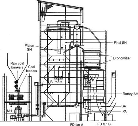
Figure 13.30 shows an industrial PF non-RH semi-outdoor bidrum boiler with corner firing and the rotary AH. Designed for high-ash coal, it has four mills, including one standby. Tangential burners are used. Design pressure is <140 bar and a bidrum construction is used for BB. The SH temperature control is by a combination of attemperator and burner tilt. The arrangement is compact, with all surfaces accommodated in two passes. This is
|
FIGURE 13.30 Typical 75 MWe (270 tph) corner-fired PF bidrum boiler. |
Made possible by the rotary AH, which snugly fits under the ECON. With a tubular AH, the arrangement would have demanded a third pass.
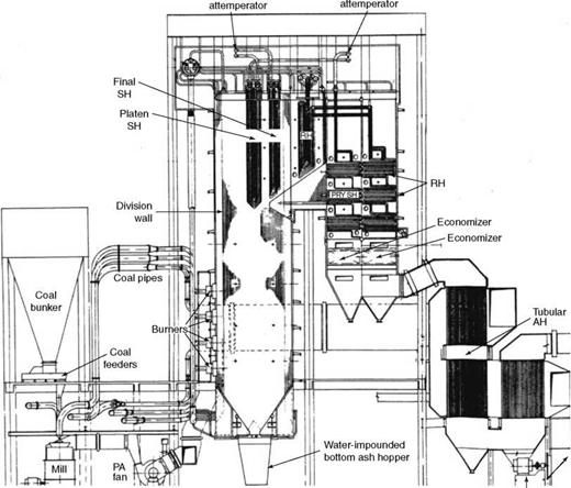
Figure 13.31 depicts a typical 210 MWe or 680 tph RH boiler with front-wall firing and a large tubular AH for high-ash coals. Normally, six mills are employed. Front wall firing is adopted. In double-wall firing, the furnace would have been shorter but deeper. This is a classical twin rear-pass design with RH and SH located in different passes, with dampers to bias the gas flows. The RH temperature is controlled by regulating the gas flow in the RH pass, whereas the SH temperature is controlled by a combination of spray attemperation and selection of burner level. A division wall is employed to increase the furnace surface without correspondingly raising the furnace volume. A combination of platen and pendant SHs is used for achieving the final temperature. A two-stage attemperator is employed to give a good turndown with a wide range of coals. Oil firing is limited to startup and load stabilization only at 25% MCR capacity.
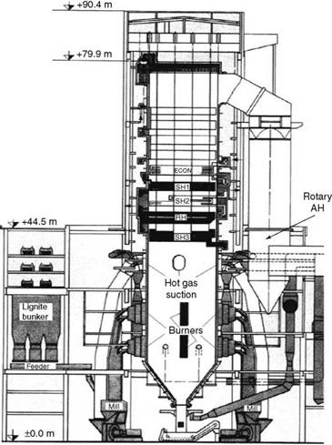
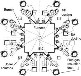
Figure 13.32 shows a typical tower-type boiler for lignite firing with four beater mills. Unlike coal-fired boilers, it is usual for lignite and brown coal-fired units to have the four mills at the four sides or corners of the boiler. It is normal for high-moisture lignites to adopt tower-type furnace construction with no gas turns on the convection banks to
|
Second-stage First-stage
ID fan FIGURE 13.31 Conventional two-pass PF boiler with twin rear passes and front firing and division wall. |
Minimize erosion. With tower-type design, all the banks are fully drainable. This construction also facilitates the layout of mills. Hot gas for lignite drying and transport is drawn from the furnace exit. Only the AH is in the second pass. The bunkers are rather small in these boilers, with —5 h of storage capacity to prevent spontaneous combustion of fuel common with lignites.
The feeders are plate type and not drag link, as the fuel tends to break very easily. In plate feeders, the fuel is carried on the plates and not dragged by feeder slats.
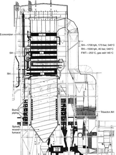
Figure 13.33 depicts a 500 MWe 1600 tph boiler for coal firing, with highly abrasive ash at a pithead location. Horizontal ball mills are employed for a better life, as mill wear is a serious concern with alpha quartz in coal ash here. High mill power consumption is countered by using the plant at base load, with little fluctuation on the lower side. For the same reason of erosion, the tower-type construction of pressure parts (PPs) is used. Subcritical once-through (OT) design pressure conditions achieve slightly better cycle efficiency.
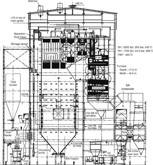
The 660 MWe SC OT boiler, shown in Figure 13.34, is a conventional two-pass design with opposed firing. Vertical mills, typically 10 in number, are arranged in two rows on
|
FIGURE 13.32 A 210 MWe lignite-fired tower-type boiler. |
*0
5Ґ
Гй
N*
Su
?
3!
|
|
Os
О
|
FIGURE 13.33 A 500 MWe tower-type corner-fired subcritical once-through boiler with tube mills for high-ash coal. |
Either side of the boiler for a better layout of coal piping to both front and rear walls where burners are mounted. The twin rear-pass design may be abandoned in favor of a single pass. Consequently, the rotary AH is arranged in the third pass because of less width of second pass.
Pulverized firing boilers are made in a variety of configurations. An attempt is made to introduce some of the popular designs to provide an over view of the complexity of the subject.
|
FIGURE 13.34 A 660 MWe two-pass opposed fired vertical tube SC boiler for high-ash coals. |
Further Readings
Bennett, A. L., 1986, Coal flow and design considerations, Stock Equipment Company, January. Brundiek, H., 1989, The roller grinding mill—Its history and current situation, AufbereitungsTechnik, December.
Harstein, G. E. and Williams, D. C., 1978, Industrial pulverised coal fired boiler designed to meet today’s challenge, presented at American Power Conference, April.
Johns, P. T., Clocker, R. A., and Levstek, D. F., 1984, Modern utility boiler designs for low grade coals, B&W International Division, paper presented at PRC.
Lin, Q. and Penterson, C., 2004, Coal pulveriser design upgrades to meet the demands of low NOx burner operation, Electric Power, April.
Livingston, W. R. and Dugdale, K. L. Modern coal mill design and performance, Mitsui Babcock Energy Limited.
Mill feeders and pressure relief in fossil fired thermal power stations, Paper presented by Babcock of Germany in Shenyang, PRC, August, 1985.
Miller, K., 1997, Tube ball mills for modern coal firing systems, Deutsche Babcock, July.
The HP mill series—A new generation of combustion engineering mills. Sales literature, Combustion Engineering Inc., Windsor, CT, USA.
Tigges, K. D., Bischoff, W., and Steinhage, T., 1998, Ring and roller bowl mills as components of modern firing technology, VGB Power Technology, Babcock Kraftswerkstechnik Gmbh, February.


 14 сентября, 2013
  admin
admin 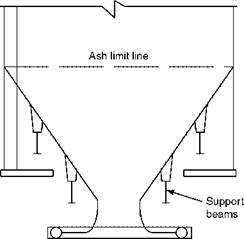
 Опубликовано в рубрике