Soot blowers are installed in most boilers for the removal of entrained soot and ash susceptible to slagging and fouling. Natural gas (or such clean fuel)-fired boilers are exceptions because there is no ash in the fuel to deposit on the HSs. Soot blowers remove.
1. Soot and ash deposits from the fire sides of HSs so that they remain optimally clean and heat transfer is maintained at the original design levels
2. Ash deposits from the gas passages between the tube rows so that the gas side pressure drops stay within the design limits
The overall cooling of flue gases and gas pressure drops stay close to the original figures to maintain the performance. Besides ensuring a proper heat transfer, the progressive pluggage of gas passes is avoided. Plugged sections lead to gas flow restrictions causing (1) load limitation and (2) tube erosion in the lanes where the gases flow at increased velocities.
Larger boiler sizes require more blowers. High-ash coal, lignite, and BL recovery boilers require numerous blowers of all types. For blowing purposes, the entire set of blowers is considered as one lot and blown in one set sequence and never in isolation. Soot blowing is always in the direction of gas flow so that the ash is carried toward the banks that are yet to be blown. High-ash coals with low-ash fusion temperatures and high Na are the most difficult to clean.
Oil firing, with its low-ash content, produces thin water-soluble deposits in the furnace and friable ash deposits on the SH and RH. The furnace deposits are removed in annual water washing, and no wall blowers are needed. In the convection section, the deposits are sizable with high-vanadium oils because of the additives used for minimizing high — temperature corrosion. These deposits are easily removable by SBs.
Working Principle of Soot Blowers
Soot blower is a device that directs a stream or a number of streams of cleaning medium at the ash deposits so that they get dislodged by the impact of the jets. Called as the peak impact pressure (PIP), it is the energy at a certain distance from the nozzle of the SB. The PIP depends on the
• Nozzle size and configuration
• Fluid pressure and temperature
Soot blowers consist of four parts:
1. Nozzles for blowing the fluid
2. Element (or lance in longer SBs) for conveying the fluid
3. Drive system for rotating or advancing/retracting the element
4. Control system
Cleaning fluid in SBs can be steam, air, or water. Steam is the most popular and available.
• Steam for soot blowing should be dry under all conditions to prevent impingement of heavy water particles that can render serious damage by way of erosion or puncture.
• Saturated steam helps to deliver a high PIP. Ideally, there should be 10-20°C of superheat.
• Higher superheat is also employed. The steam gets lighter but the jet velocity increases, making the PIP higher and resulting in a better cleaning.
• The pressure of steam is first reduced in the poppet valve placed just ahead of the lance to restrict the blowing or nozzle pressure to <5-25 barg (—75-350 psig), depending on the actual configuration.
• Several stages of pressure reduction take place before the steam emerges at the prevailing draft inside the boiler setting. Steam from the nozzles is at supersonic velocity.
• A poppet valve has an adjusting nut for varying the blowing pressure, and each SB is set for the best result depending on the type of ash deposits. Tenacious deposits need a higher pressure. For fluffy deposits, the pressure should be lowered to prevent tube damage.
• SBs are practically ineffective on any flowing low-viscosity slags, such as those found with oil firing, as there are no deposits to blow away.
Air is also used for cleaning; see Section 8.9.4. Compressed air at —25 to 35 barg (—350 to 500 psig) is required for blowing pressures of 4-15 barg (—60 to 215 psig).
Water is used occasionally alone or in combination with steam or air. Water pressure required is 10-20 barg (—150 to 300 psig). Water is also occasionally injected into the retractable SBs to keep the lances cool. Such blowers require different types of nozzles.
The drive motors can be either electric or pneumatic, with the latter used in refineries and similar areas with stringent requirements of fire protection.
Types and Locations of Soot Blowers
There are basically four types of SBs: (1) wall/short retractable, (2) rotary, (3) retractable, and (4) rake-type blowers, meant for different parts of the boiler. Table 8.3 presents the main features of the SBs. Figure 8.57 shows the SBs in a PF boiler and their locations.
Boiler Firing and Soot Blowers
Not all types of boilers require SBs.
• Gas-fired boilers with no ash deposits have no blowers.
• PF boilers with coal burning at high temperatures produce molten ash that deposits itself at all locations, requiring blowers at all locations.
|
TABLE 8.3 Soot Blower Types and Characteristics
|
|
Note: Cal = calorised, Fess = ferritic stainless steel. |
|
FIGURE 8.57 Soot blower locations in a large pulverized fuel boiler. |
• Fluidized bed combustion (FBC) boilers, with low-temperature combustion, do not melt the ash and hence are free from the slagging and fouling problems of PF boilers. Naturally, they do not need SBs furnace and SH/RH regions. Some boilermakers install SBs in the ECON and AH areas, whereas the others increase the HS and dispense with SBs, as the deposits are dry, loose, and friable.
• Stoker-fired boilers operating with relatively lower furnace temperatures do not slag and hence need no wall blowers for coal or for biofuels. However, with combination firing of coal and biofuels, the melting temperature of ash eutectic is often low enough to warrant installation of wall blowers to clean slag deposits.
• Oil-fired boilers, with their closely spaced tubes in various tube banks must blow off the fine ash, and rotary blowers are usually adequate for this blowing. With heavy metals in ash, such as vanadium, which are in molten form at high furnace temperatures, retractable SB at a furnace exit is often required to keep the SH tubes clean. But at temperatures above 950°C, fuel oil additives are required to raise the melting temperature of the ash. Wall blowers are of no use as the ash is molten.
• Heat recovery steam generators are free of SBs despite closely spaced fins on tubes, because they usually fire clean fuels.
• Waste heat recovery boilers usually need SBs, as they deal with dusty process gases.
Steam is the most common blowing medium due availability. Compressed air can also be used as the effectiveness is nearly the same. Air blowing is considered when
• Steam and water leakage can be problematic as in the case of BL recovery boilers (due to smelt-water explosive reaction).
• There is a need to conserve the expensive-treated FW as in high-pressure boilers or in areas of high water shortage.
• The tenacious ash deposits require an almost continuous use of retractable SB, which consumes —15 tph of steam, and the boiler steam production is not large enough. This is typically the case with some WHRBs.
In very large coal-fired boilers, air blowing is preferred as the soot blowing consumes high-quality expensive water. For air blowing, an elaborate arrangement consisting of a proper air compressor station to deliver high-pressure air between 25 and 35 barg (—350 to 500 psig), with all redundancies, controls, and safeties, is required, which is reasonably expensive. But the air piping is simpler and requires fewer valves and fittings.
The unique advantage of steam blowing is that any additional SBs required to be added are easily accommodated in steam blowing as steam is available.
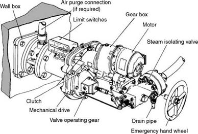
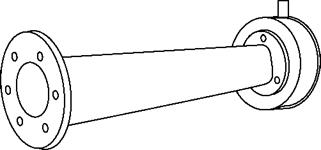
Wall blowers, deslaggers, and short retractables, (Figure 8.58) are installed on the furnace walls for the removal of slag deposits. In high-temperature furnaces, such as in PF firing, where the furnace temperatures exceed the ash fusion temperatures and the ash is in molten condition, deposit formation on ash contacting the cool furnace walls is
|
FIGURE 8.58 Typical wall blower/deslogger/short retractable. |
Inevitable and must be removed periodically; and wall blowers perform such duty. At the highest gas temperature, the blowers enter the furnace for a short distance of —40 mm from the wall tubes and blow backward toward the wall. The total operation of wall blower lasts for <2 min of which the actual steam-blowing duration is less than a minute and the complete blowing consists of one to three revolutions. Steam flow at 3.5 tph (60 kg/min) delivered through one or two large nozzles of —25 mm 0 is sufficiently forceful to dislodge the semimolten ash. Depending on the type of firing, boiler size, fuel type, ash in fuel, slagging potential, previous experience, etc., a number of blowers are installed on a boiler furnace. Approximately one blower is required for every 10 m2. The nominal blowing length is —1.5 m, which is reduced to even 0.75 m in case of very heavily slagging coals.
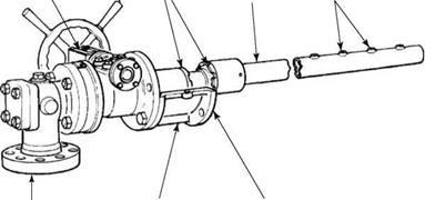
Rotary SBs (Figure 8.59) are employed in low-temperature and low-deposit zones where ash cleaning does not demand high-impact pressures from the jets. A typical rotary or stationary SB has a 40-80 mm 0 lance with a number of small nozzles of 6-10 mm 0 (average 8 mm) welded on it with steam blowing through them while the lance rotates. The lance is made of suitable metal to withstand the gas temperature. Unlike in retractable SBs, the lance in rotary SB does not rely on steam to cool it. As the maximum temperature limit is below 1100°C, rotary SBs are located mostly in primary banks of SH, BBs, ECONs, and horizontal AHs. Lance lengths are limited to —7 m as the steam flow at the last nozzle beyond this length becomes too small to be effective. The rotary SBs are supported from the tubes at suitable intervals to prevent their sagging and hitting the adjacent boiler tubes. For boilers larger than 7 m, the rotary SBs are placed from both sides of the boiler. Rotary blowers can be manual or motor-operated.
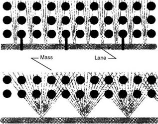
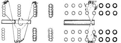
Mass and lane blowing (Figure 8.60) are the two methods of steam blowing from rotary blowers. In mass blowing the tube spacing is wider, and there is a cavity large enough to
Position
Indicator Hand wheel
|
Flexible couplings V Element/lance Steam nozzles
Steam Coupling case Mounting flange Isolating valve FIGURE 8.59 Manually operated rotary soot blower. |
Accommodate a certain distance from the tube surface. In lane blowing, the cavity is too small as in BB and the steam nozzles are set along the tube lanes. Lane blowing requires more and smaller nozzles. Also, the axis of the blowers has to be perpendicular to the tube axes. In mass blowing, the two axes can be parallel or perpendicular.
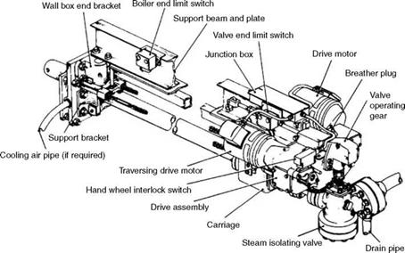
Retractable SBs (Figure 8.61) are the most advanced types based on performance and mechanical considerations. As the lances are required to clean the SH and RH platens and
|
|
FIGURE 8.60
Lane and mass blowing.
|
FIGURE 8.61 Fully retractable soot blower. |
|
FIGURE 8.62 Soot blowing patterns for platens and pendants. |
Pendants in the highest gas temperature zones, they cannot be left inside the boiler as in the case of rotary blowers. They have to be fully retracted.
There must be a free space on the sides of boiler for retractable blowers, and the distance from the adjacent boiler is generally governed by this parameter. These blowers are motor driven with a back-up hand wheel drive to withdraw the lance from the boiler in case of motor failure, lest the lance should be deformed and damaged due to heat. There are usually two motors in every retractable blower, one for rotating the lance and the other for advancing or retracting the lance. The lance is a 60-80 mm diameter pipe with a pair of steam nozzles (to balance the forces) located on both sides in exact opposition or at an angle, depending on the cleaning required. The slanted holes are usually for platens as this can give a better dwell of the steam on the tubes. This is shown in Figure 8.62. The blowing pressures are 4-12.5 barg (—60 to 180 psig) for air and 5-25 barg (—75 to 360 psig) for steam with typical nozzle sizes of 16 and 22/25 mm
0, respectively.
At the end of the travel, the lance is given an offset so that the return path is on a different helix for a more complete coverage of the jets. Typical helix patterns vary from 100 to 125, 150, and 200 mm (—4, 5, 6, and 8 in.) depending on the travel. The diameter and thickness of the lance and the support system should maintain straightness at the farthest travel lest the end of the lance should foul with the tube. Increasing the cavity between the tube banks is not possible. Very rigid construction of the SB is therefore needed.
The steam flow through a retractable SB is generally 4 to 20 tph. In other blowers, the duration of blow is much shorter at <1 min, and the flows are also smaller at <4 tph. If the steam flow from boiler is to be maintained, the boiler has to go into an overfiring mode to compensate for heavy steam flow through the retractable SBs, particularly in industrial boilers.
• A massive blow must be delivered to the sintered ash deposits in the SH and RH regions.
• Steam acts as a coolant to the lance that may be required to stay up to 30 min inside the hot boiler casing in large utility boilers. Many times the flow is decided more by cooling requirement than by blowing.
• For the platens located in the temperature zone, where there is more of slagging than fouling, the steam flow should be large enough to set the platens into a mild swinging motion to let the semisolid ash to drop off.
The rpm and translation (advancing and retracting) speeds of the SB are selected from previous operating experience to keep the lance cool. Typical translating speeds vary from 1 to 5 m/min (—3 to 15 ft/m). A combination of rotational and translation speeds along with helix distance delivers the appropriate cleaning force for each zone.
Half-retractable and one-third retractable blowers are also required for cleaning in the parallel passes during the second pass where the gas temperatures are low enough to locate the blowers inside the setting. Cleaning with two or three pairs of nozzles is far more powerful than that achieved by using many nozzles of rotary blowers. The blowers traverse half or one-third the distance.
Rake-Type SB
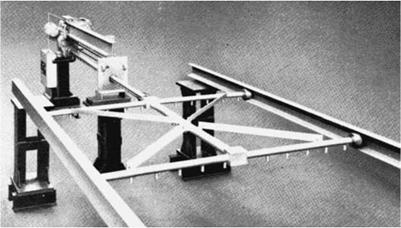
Rake-type SBs are used in the second pass of the boiler for cleaning the fin tube ECONs and vertical TAHs. Steam tubes with accurately located steam nozzles move on a track. The cleaning is far more efficient than with rotary SBs with better penetration. Rake length and width are usually limited to 5 and 3 m (—16 and 10 ft), respectively (Figure 8.63).
For small rotary airheaters (RAHs), one or two rotary SBs are fixed in the gas side of the AH at the gas inlet or placed additionally on the gas outlet side. For larger AHs in utility boilers, retractable SBs are installed at the inlet and outlet ends to provide deeper penetration of the steam jets for a better cleaning. Rake-type blowers are also used.
With heavy slagging and fouling of coals, sometimes the SBs are not fully effective in dislodging the ash deposits. As a last option, lancing with high-pressure water is adopted, as water can deliver a better blow than steam. The water jets are directed to the ash deposits, carefully avoiding the tubes to prevent thermal shock and failures. Water lancing requires great precision.
|
FIGURE 8.63 Rake-type soot blower for economizer and tubular airheater. |
|
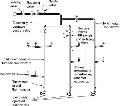
FIGURE 8.64 Typical piping for soot blowers. |
Figure 8.64 shows piping for SBs. A hand-operated isolating valve is always necessary to isolate the entire system for attending to any problem. A reducing valve, followed by an SV, is usually needed as the blowing pressures are lower than the steam pressure at source. The source can be the primary SH header, final SH header, cold RH line, or hot RH line. The choice is more complicated in boilers operating with variable pressures. Most boilers adopt the primary SH header.
Condensed steam in pipelines hitting the tubes and causing damage is a serious concern. All SB feed lines are given a slope of at least 1° in the direction away from the blowers. The blowers are branched off from the main pipes, which run vertically downward to the draining system, so that the feed tubes are free from water particles. Soot blower control logic starts with dry steam in piping for which the draining has to take place long enough for thermostat to give a reading same as the saturation temperature. Soot blower operation can commence only thereafter. The SBs are grouped and fed with pipes.
Acoustic or Sonic Soot Blowers
In acoustic or sonic blowers (Figure 8.65), sound waves are generated at low frequencies to produce rapid pressure fluctuations, causing vibrations in the ash deposits, which get loosened from the tubes and fall into the gas stream. They should not be too sticky or hard.
|
FIGURE 8.65 Wave generator and bell section of acoustic blower. |
These blowers are ineffective over slagging or sintered deposits. Thus, the sonic horns are blowers for the second pass of the boiler for cleaning the dust from the low-temperature SHs, ECONs, and tubular AH.
A standard plant compressor generates the required compressed air to produce powerful sound waves as it enters the wave generator and forces the only moving part of the system, namely, the titanium diaphragm to create a powerful base sound wave that is transmitted by different bell sections to produce sounds of selected fundamental frequencies. Acoustic blowers consist of wave generators and resonance sections or an amplifiers.
Sonic SBs have the advantages of practically no maintenance, as there are no moving parts other than the diaphragm. The operation and installation costs are also low. Unlike the steam or air SBs, which operate with short bursts and high energy, the acoustic blowers operate with comparatively low energy levels but steadily because it takes time to resonate the ash deposits and dislodge them. This is better for installations with ESPs as the outlet concentration can be maintained with no objectionable spikes during soot blowing. Sonic horns are popular with CFBs, as the cleaning is required only in the second pass and the ash is usually in the form of loose deposits. They may not be suitable for high-moisture lignite-fired boilers where the moisture may help the ash to attach to the tubes.
Sonic blowers can also be employed in bag filters, ESPs, silos, and bins.


 31 августа, 2013
  admin
admin 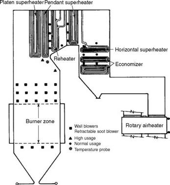
 Опубликовано в рубрике