Except in the case of package boilers and small-field erected boilers of up to —50 tph, the boiler structure constitutes the heaviest single subgroup and contains the maximum number of subassemblies and individual parts. Pressure parts and firing equipment are distinctive to the boiler, whereas the structure defines the delivery schedule of the whole plant. This is because the structural layout and design cannot start before the
1. Boiler arrangement and auxiliaries are properly completed with approvals.
2. Pressure part layouts and design are finished and approved
What is begun nearly at the end has to be completed first, because the boiler erection begins with the columns. Ironically, even in structure, the columns are the last items to be designed. Simplification of structural activity is, therefore, the key to reducing time to boiler delivery.
Structural design is governed by the building codes. The calculations are mostly repetitive and iterative and hence are amenable to computerization. But the underlying concepts and considerations must be understood in depth to ensure economical design.
1. Indoor or outdoor. This is site-dependent and customer-dependent.
A. In cold climates, indoor boilers are necessary for the comfort of operators and protection of equipment against rain and snow. Most plants in Europe and North America utilize indoor structures.
B. In warm and dry climates, outdoor units are popular if rainfall is scanty. Plants in the Middle East and many parts of Africa are outdoor units.
C. In warm climates with rainy spells, semioutdoor units are preferred. A hood on top of the boiler and firing floor prevent rain water ingress. Plants in India, China, and Latin America fall in this category.
Indoor boiler structure is the lightest because the boiler house shields the boiler from the wind loads.
2. Coastal. Corrosion is the main concern. For boilers operating on the seacoast and in plants pervaded by corrosive gases, protection of the structure against corrosive environment is done by adding corrosion allowance or by coating with epoxy paint of suitable thickness.
Loads to be Supported by Structure
The first step in the design of the boiler structure is to estimate all the loads in the boiler that need to be transferred to the supporting system:
• Pressure parts and water in them
• Buckstays and tie bars and allied attachments
• Insulation, refractory, casing, and penthouse
• Firing equipment supported on walls
• Slag and ash
• Bed material in case of fluidized bed combustion (FBC) boilers
A margin between 5 and 10% is added as a safety against outages, later additions, underestimates, and so on. These weights are, in a top-supported boiler, first transferred to the top girders, then are in turn transferred to the main columns. A lot of other loads placed on various floors are also transferred to the columns but at different levels.
In the bottom-supported boilers, these weights are transferred to the ground by the PPs. The structure is, therefore, not so much for boiler support as for providing access to all levels and may transfer the loads of the PPs where they do not rest on the ground level.
In addition to supporting boiler loads, the structure is also required to withstand external loads. These are nature-imposed loads dependent on the geographical location, for which necessary guidelines are given in the local construction codes.
• Wind loads
• Earthquakes
It is important to know the fundamental difference between the effects of wind and earthquake, although both are horizontal forces. Wind loads act on the entire height of the structure, whereas an earthquake acts at the bottom, similar to the pulling of a carpet on which a person is standing. The wind forces are relatively more steady, whereas the earthquake forces alter in direction.
Wind loads play a great role in the weight of the final structure.
• The structure is heavier for the same wind velocity as the boiler height increases. Conversely, for the same height of the structure, the weight is higher for higher wind velocities.
• Bracing all the columns and presenting an interlaced space frame is the best way to share the load and reduce the weight of the members.
• Wind loads are usually more severe along the seacoast where hurricanes and typhoons are more frequent.
Earthquake forces require remedial measures, such as earthquake restraints in the structure. Depending on the total height of the boiler, the furnace is divided into two, three, or four segments along its height, and each segment is restrained in both axes by rigidly connecting the buckstays to the outer beams.
Differential thermal expansion of the PPs and the hot structural parts is an inherent feature of any boiler. Many structural problems in the static parts of the boiler arise from differential thermal expansions. To minimize these problems, it is necessary to
• Anticipate the expansions
• Make adequate provisions for the expansions
• Guide them suitably
The top-supported boiler expands downward and the bottom-supported upward. An expansion diagram for the PPs is drawn and the structural guides are provided at the design stage.
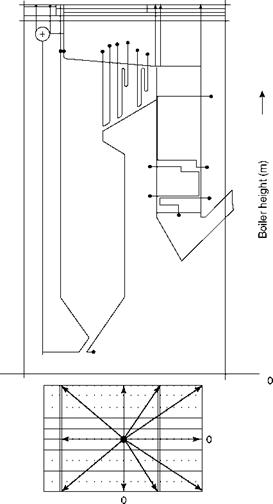
In Figure 7.14, the expansions of the PPs are estimated and drawn for a top-supported PF boiler. The boiler is anchored in the center with equal expansions on all the sides. A boiler can be anchored in any way that is suitable for the site layout—at the center, front, rear, or left or right side.
Likewise, a boiler can be supported either from the bottom or from the top. Medium and large boilers are always top-supported. When hung from the top, the vertical expansion is always one way—downward. Also, the maximum expansion is experienced by the furnace. The two lines at the right side of Figure 7.14 depict the following:
1. Thermal expansion of the PP
2. Expansion with settlement after water is added
Coefficient of thermal expansion of steels in the temperature range experienced by the PPs can be conservatively considered as —1 mm/m/100°C. This varies depending on the steel and the temperature range but is good enough for quick estimates. For a boiler with drum at 45 m and operating at 160 bar pressure (347°C saturation temperature), the thermal expansion of the bottom water-wall header at 4 m level will be —130 mm. Such a large expansion must be provided for, and for all connecting equipment at various levels, appropriate downward movements should be transmitted safely. Suitable guides are
-PP
|
Thermal expansion (mm) |
![]()
|
Direction of expansion |
![]()
|
FIGURE 7.14 Typical thermal expansion of a top-supported two-pass boiler. |
![]()
|
I |
![]() PP with water
PP with water
Provided at various levels in the structure to guide the vertical expansion of the furnace to prevent interference from uncontrolled movements.
Boiler structure is usually divided as follows:
1. Hot structure
2. Cold structure
Hot structures are attached to the hot parts, usually the PPs. These are
• Buckstays and tie bars
• Top-suspension hangers
• Top-suspension girders
• Columns with base plates
• Main beams and bracings
• Galleries, ladders, and platforms
• Guides and restraints
Buckstays and tie bars. Buckstays were explained in Chapter 6 (see Figure 6.5). Buckstays experience the following loading:
1. Longitudinal loading due to internal pressure and externally applied loads
2. Normal loading due to internal pressure
3. Bending moments caused by the eccentricity of the brackets supporting the PPs
4. Temporary loading due to (1) internal explosions, (2) wind forces, and (3) seismic conditions
The buckstays have to restrain the tubes from bending and keep the furnace enclosure in position. The buckstay spacing should contain the tube deflection, and the tube vibration should not coincide with the natural frequency of three cycles per second.
Buckstay deflection is normally limited to
• L/360 for stoker and similar industrial boilers
• L/480 for PF and large boilers
Tie bars are really the hot parts, which are attached to the furnace tubes or the membrane panel. Buckstay clips or welding clips attach the tie bars to the buckstays. Buckstays should be kept as cool as possible. Care should be taken to avoid closing them with insulation.
Top-suspension hangers/sling rods. The whole weight of the boiler is transferred to the top girders by means of suspension hangers or sling rods. Top girders have several pairs of supporting beams from where the sling rods are suspended. The other ends of the rods are attached to the top headers or the roof tubes. Cup-spring assemblies are used with varying numbers of springs to prevent sagging of the headers in the middle.
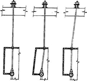
Figures 7.15 and 7.16 depict the suspension rods in small and large boilers. In the smaller boilers, the system is simple and the rods are rigidly held between the girders and the PPs. In larger boilers, the rods are much longer, and they have to overcome the differential expansion problems created by the penthouse by having a more elaborate sealing. The penthouse is the enclosure for risers above the furnace roof. Figure 7.16 shows the way the rod behaves from cold to running condition during start-up in a penthouse with hot casing, that is, casing insulated from outside. The rods have to be analyzed for these various conditions together with the expansion restrictions imposed by their sealing arrangements.
Suspension rods mostly are made of CS and are designed to a temperature of 400°C except for those connected to the PPs (SH and RH) at a higher temperature, in which case the metallurgy of the two is matched. If gas leakage is expected into the penthouse, the rods are made of alloy steel with a design temperature of 450°C.
|
|
|
|
|
Cold |
|
Start-up |
|
Normal |
FIGURE 7.16
Typical suspension rods in a utility boiler.
|
|
|
Solid sling |
 FIGURE 7.17
Drum slings.
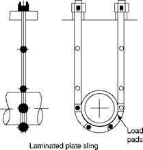
Drum slings (Figure 7.17) are different in construction from sling rods. Only two suspension assemblies are used at either end of the steam drum. The two designs of drum slings are:
1. Bar/solid slings
2. Fabricated-plate slings
A. For weights up to —200 t, it is possible to use solid slings made of high-tensile bar material. These are solid rods of 50-150 mm diameter, depending on the weight to be supported. As single rods for meeting such lengths are not usually available, they are made by joining two or three pieces to obtain the required length by welding, which is followed by stress-relieving and radiography.
B. For larger drum weights, laminated plate slings fabricated from plate steel are used. Typical weight taken by a pair of plate-type slings is as high as 1100 t in a 660 MW boiler. Plate slings fit the drum profile more closely than rod slings.
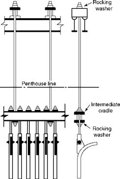
Intermediate cradles. To reduce the number of penetrations and correspondingly the sealing arrangements in the penthouse, it is usual to adopt intermediate cradles. They are particularly suitable for roof tubes. A set of tubes is slung from an intermediate cradle, which, in turn, is suspended from the top girders (Figure 7.18).
Top-suspension girders are at the highest elevation of the boiler, resting on the top plate of the main columns. The entire weight of the boiler is transferred to them. They are the deepest girders in the boiler and, therefore, have to be necessarily fabricated, except in case of small boilers. The suspension rods are hung from the cross girders, which are welded to the main girders. The main and the cross girders together form a grid at the top, collectively known as the top suspension grid.
The top girders, as they merely rest on the bearing plates on the top of the columns, are treated as simply supported beams. Typically, the limiting deflection is very small at L/700 so that the connected parts experience minimum sag.
|
|
FIGURE 7.18
Intermediate cradle for roof tube support.
Columns. The base plates are fixed to the ground by means of foundation bolts, making them behave like members fixed at one end and free at the other. In addition to the vertical loads and bending moments at the top, the columns are subjected to forces and moments at every beam level. The column design, therefore, can proceed only when all the framing is complete with all details of the equipment location properly determined and the piping routing with hangers completed accurately.
The number of columns for the boiler is an important decision. Columns at the four corners of the furnace give an uncluttered arrangement and free maintenance space at the ground level, but the top girders must be heavy. In multicolumn design, columns and the top girder become lighter. Normally, in spite of more members, the multicolumn design is less expensive.
In the multicolumn arrangement, the top girder changes from simply supported to a continuous beam with multiple supports. Figure 7.19 depicts both the cases for a large two- pass unit. The types of firing and ash handling equipment decide the number of columns best suited. In bidrum boilers, it is common to have a pair of columns on either side of the bank. In tower type boilers and many two-pass units, the columns are at the four corners.
Column spacing is an important layout consideration. In plan view, the columns should extend beyond the furnace casing by 1-2 m to accommodate the integral piping, particularly the large interconnecting piping and downcomers with their insulation and fittings. In PF boilers, mill piping is contained within the columns. This is not important in small bottom-supported boilers as the columns are short and the load points decide the location.
|
||||||||||||||||||||||||
|
||||||||||||||||||||||||
|
||||||||||||||||||||||||
|
||||||||||||||||||||||||
|
||||||||||||||||||||||||


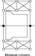

The outer columns carry the galleries and ladders and necessarily extend to the top of the boiler.
Beams and bracings. The two types are:
1. Main beams
2. Floor beams
Main beams are the big load carriers and straddle the columns. They are either welded or bolted to the columns. Floor beams, however, carry the floor loads and any equipment resting on the floors and hence are lighter.
Bracings connect the columns diagonally and they distribute the dead loads and the wind loads, so that the structural load distribution is better and the structure is lighter. Locating the bracings is always unsatisfactory as they interfere with free movement in the affected floors and galleries. Airheater tube withdrawal usually causes problems with bracings. Sometimes bracing of columns has to be avoided in a section, as shown in Figure 7.20, due to access considerations.
7.4.1 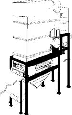
|
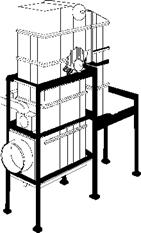
FIGURE 7.21 Top, middle, and bottom supports for bidrum boilers. |
![]() Top, Middle, or Bottom Support
Top, Middle, or Bottom Support
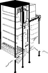
Boilers can be supported from the bottom, middle, or top as shown in Figure 7.21. Package boilers, pre-engineered oil — and gas-fired boilers of even large size, and solid fuel-fired boilers up to ~ 60 tph can be bottom-supported. In the bottom-support design, the supporting structure is very light or nonexistent for units like package boilers. Some supporting structure around the boiler is required for providing access. The PPs act as load carrying struts and transfer the loads to the ground.
Beyond a certain size as the boilers become tall, the differential expansion increases and the weights also increase, making it cheaper to adopt top support. Top-support design can be likened to a church bell. As the weight of the bell is suspended from the casing, the entire PP assembly of the boiler is suspended from the structure, which encloses and transfers the weight to the ground. The PP assembly, now slung from the top girders, is free to expand downward and move sideways. Naturally, the top-support design is more expensive, although it is easier to design.
There are certain designs amenable to a middle support, also called a girdle support, where the boiler is supported at some midpoint, allowing thermal expansion to take place. Stoker — fired boilers fall in this category.
Irrespective of top or bottom support, a heavy item such as the AH (both tubular AH [TAH] and rotary AH [RAH]) is supported from the bottom. The ECON is also supported from the bottom in most bidrum designs as it is placed in the second pass above the AH. However, it is slung from the top in single-drum radiant or tower-type boiler designs.
Whether to adopt a welded or a bolted design is a difficult choice. Bolted or welded refers to the type of joints the ends should have. Bolted construction is heavier and more expensive due to
Additional jointing material (support stools and gusset plates) and fasteners Shop fabrication and trial assembly Heavier construction
Bolted construction renders erection very easy and fast. If the erection costs are high, the overall cost works out nearly the same as the welded design with the added advantage of faster and error-free erection. Welded construction is more popular, although it requires more erection time, welding, and manpower, because:
• There are no additional jointing materials.
• It is lighter because it is part of an integrated structural framework.
• It is easy to correct at site.
The practice followed by the boilermaker or the preference of the customer usually decides this issue of welded versus bolted structure.
Rolled Beams or Built-Up Sections
The top suspension girders must be fabricated as they exceed the limit of rolled sections. Likewise, the main columns and certain heavy beams of medium and large boilers are also required to be fabricated. With greater availability of H and WF sections, it is now possible to adopt rolled sections and reduce the fabrication, at least for the main columns and the beams of utility boilers. But the specific cost of the extra-deep sections is higher and the delivery time longer. Deep sections for main columns and certain beams are fabricated using thick plates at nearly the same cost.
Further Readings
Killicaslan, M. and Babcock, D., 1991, Summary of symposium about the design of natural circulation boilers for power plants, Power, March.
O’Keefe, W., 1981, Reliable dampers: vital for today’s power plant, A Power Special Report, October. O’Keefe, W., 1992, Benefit from user experience with non-metallic duct joints, Power, August.
Tracey, P. L., Constructional Features of Large Natural Circulation and Once Through Boilers, Babcock and Wilcox (Operations) Ltd.


 28 августа, 2013
  admin
admin 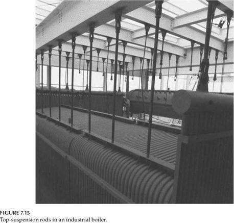
 Опубликовано в рубрике