The efficiency of the steam cycle is improved by higher steam pressure and temperature as well as reheating. Both superheating and reheating of steam have to be as high as possible. At a steam pressure of 120 bar and higher, the cycle efficiency improves by —1% for every 20°C rise in superheat. Therefore, high superheats are desired for each band of pressure consistent with the metallurgy of the turbine.
• In smaller power ranges, 485, 510, and 530°C (905, 950, and 985°F) are the popular SOTs.
• For utility applications, 540°C (1005°F) is the most common.
• The 565°C (1050°F) is becoming prevalent in large heat recovery steam generators (HRSGs), and in subcritical boilers for RH.
• In ultra-SC (USC) applications, 620°C (1150°F) is used.
Beyond 540°C, the metallurgical issues assume a great importance. The most complicated parts of the boiler are the SH and RH because:
• They are located in the hottest gases (either inside or immediately after furnace).
• The coolant is not saturated water but steam, whose cooling effectiveness as measured by the film conductance is far inferior to that of water, making SH and RH attain the highest metal temperatures.
• At those temperatures, their sizing has to be very exact because the margin of error for overheating is limited.
• The disposition of surface should take into account the effects of gas-side slagging, fouling, erosion, and corrosion.
• Unbalance of steam flow and variation of gas flow across the boiler width have to be factored in, on top of upset conditions in gas temperatures, to arrive at the tube metal temperatures for material selection. Steam flow unbalance (elaborated in Section 6.3.7) is the variation of flow across the SH elements compared to the average flow. Upset conditions are the FEGT excursions due to furnace slagging or overloading.
• Appropriate steam temperature controls (STCs) have to be incorporated individually for SH and RH.
In a subcritical boiler, the SH is between the main-steam header and the steam drum and consists of
• Saturated tubes that transport steam from the drum to the SH inlet header (when the SH tubes are not directly connected to the drum)
• Superheater banks with their respective inlet and outlet headers
• Attemperator station for STC
• Main-steam header with all fittings and terminating with the main-steam stop valve (MSSV)
Steam from the steam drum flows toward the main-steam header, and there should be no valve between the two to ensure flow in SH tubes under all conditions to prevent overheating and failure.
Reheating of steam involves withdrawal of partly expanded steam (at the end of the high — pressure cylinder of the turbine), taking it back to the boiler in cold reheat pipes, heating to the same or higher temperature as the superheated steam, and returning to the turbine in hot reheat pipes. In terms of hardware, an RH system comprises
• Cold reheat pipe from turbine to boiler
• Safety valves on the cold reheat pipe
• Emergency spray-water attemperator system on a cold reheat pipe or interconnecting pipe
• Reheater bank complete with inlet and outlet headers
• Hot reheat pipe from boiler to turbine
Considering the required changes to the boiler and the turbine, the reheating involves a lot of expense and, from practical considerations, it is considered viable only above 100 MWe. In HRSGs, likewise, RH is employed in bigger combined cycle (CC) plants employing advanced class machines with high exhaust-gas temperatures >600°C and larger frame sizes with large gas flows. Typically, RH starts in HRSGs behind the gas turbine (GT) of frame size 9FA or equivalent with steam turbine output of >120 MWe.
A temperature of 540°C is the most popular. As the pressures in RH are lower (about one-third to one-fourth of SH), for the same stress levels in tubes, it is possible to have higher RH OTs of —20 to 30°C over SOT.
In steam power plants, the RH flow is (—2%) less than the SH flow, as there are minor leakages in the HP cylinder of the turbine. In the case of gas-based power plants, however, the reverse applies. The intermediate-pressure (IP) steam is produced at the same pressure as the RH and is added to the RH flow.
Superheater and Reheater Design Principles
Superheater and reheater are the tube banks that attain the highest temperatures in a boiler and consequently require the greatest care in the design, fabrication, and O&M to ensure that the permissible metal temperatures are never exceeded. The final sections of both SH and RH must be placed in the highest gas temperatures, which calls for adopting the most appropriate high-temperature alloy for the tubing from considerations of
• Metal temperatures
• Fouling due to ash compounds
• Corrosion due to salts in ash
The three most important aspects of the design of both SH and RH are:
1. Uniform distribution of steam and gas across all the sections to minimize unbalance of flows.
2. Optimally high steam velocity in all the tubes to keep the metal temperatures as low as possible.
3. Minimum steam pressure losses.
A. Superheater pressure drop is normally limited to —8% of outlet pressure to reduce the pumping load.
B. Reheater pressure drop is usually <2 bar from cycle efficiency considerations. This is a tough requirement, particularly where specific volumes of RH steam are three to four times higher than those of SH steam. A reheater bank is usually located just after the final SH bank in the hot gases to make it as compact as possible and contain it in a single bank between a single set of headers.
6.3.2 Superheater and Reheater Classification
Superheater and reheater can be classified from design and arrangement considerations as shown in Table 6.2.
These flows are based on the overall direction of steam flow with respect to gas flow. Individual tubes, however, are always at cross flow.
• The section is in parallel flow (Figure 6.10b) when the two flows are in the same direction and in counterflow (Figure 6.10a) when in opposite direction.
|
TABLE 6.2 Classification of Superheaters and Reheaters
|
|
A b c d
|
|
FIGURE 6.10 (a) Counterflow, (b) parallel flow, and (c) and (d) mixed-flow surfaces. |
• In parallel flow, the highest gas temperature is in contact with the lowest steam temperature, which makes LMTD a little lower and the HS a little higher. The reverse applies to counterflow. Naturally the counterflow arrangement yields the lowest surface.
• Because the highest gas and steam temperatures in counterflow coincide, the metal temperatures are at their highest.

|
A. Counterflow LMTD |
![]()
|
B. Parallel flow LMTD |
![]() Mixed-flow arrangement (Figure 6.10d) is the optimum solution that yields a good compromise—counterflow at a lower temperature and parallel flow at a higher temperature. Sometimes this pattern is reversed as shown in Figure 6.10c.
Mixed-flow arrangement (Figure 6.10d) is the optimum solution that yields a good compromise—counterflow at a lower temperature and parallel flow at a higher temperature. Sometimes this pattern is reversed as shown in Figure 6.10c.
(6.4)
Radiant and Convective Superheater and Reheater
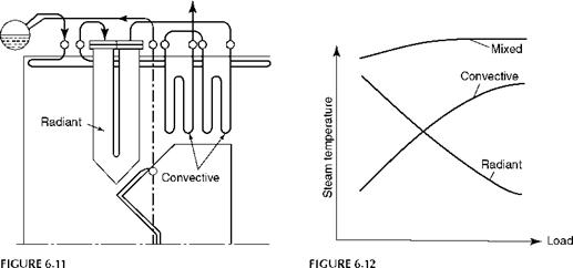
This function is based on the type of heat transfer that is predominant. Superheater and RH in a furnace are radiant. They are in the form of platens or wing walls. With increasing load, the temperature of the steam in a radiant surface reduces unlike on a convective surface, where the steam temperature rises with load. This is because the radiation incident is not much lower than that at full load, whereas the steam flow reduces proportionally, thereby absorbing greater heat and becoming hotter at low loads. The converse is true for convective surfaces. Both radiant and convective SH and RH are necessary to attain the high steam temperatures needed. Their characteristics can complement each other to obtain a fairly constant temperature at all loads with minimum attemperation (Figures 6.11 and 6.12).
|
|
|
Typical radiant and convective superheater. |
|
Radiant and convective superheater characteristics. |
Single-Pass and Multipass Arrangements
Steam should also be viewed as a coolant for SH or RH coils. Adequate velocity of steam is essential to remove the heat and keep the metal temperature in control. In other words, the steam film on the inside of the tube has to be as thin as possible so that the tube metal stays close to the bulk steam temperature. At the same time high steam flow contributes to an excessive steam pressure drop. Table 6.3 gives the recommended steam flow in tubes at various temperature levels. A desirable pressure drop between headers is 1.5-2.0 ata (20-30 psi) as a good balance.
• To prevent flow reversal at low loads
• To avoid unnecessary load on feed pumps
To achieve this end, tubes may have to be arranged in parallel in several loops along the gas flow as shown in Figure 6.13 with a two-loop arrangement. In addition, across the gas flow, steam may be carried in one or several parallel passes. This is typically the case with wide furnaces and low-CV fuels with relatively small steam production per meter length of drum, as in waste heat and waste fuel boilers.
Vertical and Horizontal Arrangements
Vertical, horizontal, and a combination of both are used for achieving the desired SH and RH depending on the boiler layout.
• Vertical tubes are easy to suspend and the tubes are free to expand. But they are not drainable, which acts as a drawback in achieving faster startup of the boiler.
TABLE 6.3
Typical Steam Mass Flows for Convective Superheaters and Reheaters
Range of Mass Velocity in Convective Banks Steam——-
Temperature (°C) kg/m2 s lb/ft2 h
370-425 330-460 250,000-350,000
425-480 530-660 400,000-500,000
480-540 660-800 500,000-600,000
540-590 950 and above 700,000 and above
|
D |
![]()
|
B |
![]() A b
A b
Ft
FIGURE 6.13
Two-loop arrangements with 1 to 4 tubes and loops.
On rapid heating, water condensed from the previous shutdown turns to steam abruptly and forms a vapor lock in certain vertical tubes, preventing flow of steam in either direction. This causes tube overheating and failure. A controlled heating is therefore needed.
• Horizontal tubes are fully drainable and hence facilitate a faster startup and superior boiler load response but require a more elaborate and expensive supporting arrangement to permit proper tube expansion.
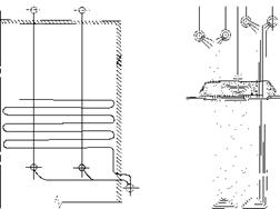
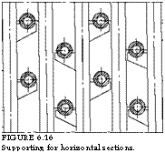
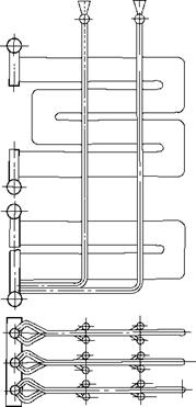
A pendant as the name suggests, is a loop with space between the adjacent legs. It is normally vertical but can also be horizontal. Figures 6.14 and 6.15 depict the horizontal and vertical pendants of single-loop and multiloop constructions, respectively. The horizontal tubes are supported by vertical tubes, usually ECON tubes, on cleats as shown in Figure 6.16. The spacing of vertical tubes is such that the sagging of horizontal tubes does not take place, lest the draining should suffer. The heat transfer is by a combination of radiation and convection, but predominated by the latter. The clear spacing between the pendants reduces with the lowering gas temperatures as the fouling tendency of the ash diminishes; hence, the need for gas velocities should be maintained. Load versus steam temperature is always a rising curve in a pendant, the slope reducing with higher amount of radiation from the furnace.
Spacing of pendants across the gas flow is decided by the fouling tendencies of the fuels. Soot blowers are necessary with dirty fuels. Retractable blowers at the furnace end and rotary blowers at lower temperatures are needed. Depth of the banks along the gas flow has to be limited to —1.7 m for coal from accessibility and cleaning considerations. Access doors for inspection and maintenance at the front, middle, and end of the banks are most essential, although this occupies valuable space.
|
FIGURE 6.14 Horizontal single-loop pendant. |
![]()
|
FIGURE 6.16 Supporting for horizontal sections. |
|
FIGURE 6.15 Multiloop vertical pendant. |
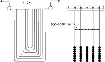
![]() In contrast, a platen is a set of closely packed tubes appearing like a plate (Figure 6.17). Platen surfaces are placed in the upper part, the open pass, of the furnace and are meant to pick up heat entirely by radiation. There is a strong slagging tendency of the flue gases in the temperature range in which the platens are located— approximately 1000-1200°C.
In contrast, a platen is a set of closely packed tubes appearing like a plate (Figure 6.17). Platen surfaces are placed in the upper part, the open pass, of the furnace and are meant to pick up heat entirely by radiation. There is a strong slagging tendency of the flue gases in the temperature range in which the platens are located— approximately 1000-1200°C.
|
|
FIGURE 6.17
Typical vertical platen.
In PF boilers, it is usual to place the platens not less than 600 mm and usually 1000 mm apart to avoid ash buildups.
Platen heaters can be vertical (hung from the roof, Figure 6.17), angular (roof to front wall), or horizontal (in tower-type boilers, Figure 6.18). Heat transfer is entirely by radiation. Platen surfaces are calculated as part of furnace open pass. The heat pickup is adversely affected as the surfaces get fouled. In PF boilers, retractable SBs are provided with the highest steam flows to maintain the cleanliness of the platens. To limit the metal temperatures, steam with little or no superheat is passed in the platens and always in parallel flow. The steam mass velocity required is also higher at —1,350 kg/m2 s (1,000,000 lb/ft2 h) or more.
In-Line and Staggered Tube Arrangement
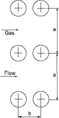
Superheater and reheater tubes can be placed in an in-line or staggered arrangement, with the latter giving a better heat transfer but more gas pressure drop, and a more compact surface on the whole. It is suitable only when flue gases are free of dust, to prevent tube erosion. The staggered arrangement is suitable for oil and gas firing whereas the in-line arrangement works for most solid fuel firing (Figure 6.19).
Tubes for Superheater and Reheater
A wide range of tubes are required in the SH construction, in terms of diameter, thickness, and metallurgy.
• Plain tubes normally used are of 38.1, 44.5, 50.8, and 63.5 mm (1%, 1%, 2, and 2% in.), with less frequent usage of 31.8 and 70 mm (1M and 2% in.) OD.
• Larger sizes are used more in utility boilers where the steam flows are high.
• The smaller the diameter, the greater the heat-transfer rate but the weaker the tube mechanically.
|
|
|
|
|
|
|
|
|
|
![]()
![]()
![]()
![]()
![]()
In horizontal SHs in tower-type boilers or vertical HRSGs, where tube supports are installed at almost every 3-3.5 m, 31.8 and 38.1 mm tubes are very popular due to reduction of HS and hence the PP weights.
Generally, 50.8 and 63.5 mm tubes are extensively used for SH application in power boilers and 38.1, 44.5, and 50.8 mm tubes in industrial boilers.
Minimum tube thickness from bending consideration is 3.25 mm (10 swg). For coal firing application, it is normal to adopt a minimum of 3.66 mm (9 swg) recognizing the erosion potential. For close radius bends, higher thickness is required depending on the manufacturing process. For higher pressures and temperatures, tube thicknesses required are considerably higher.
For finned tubes used in HRSG, the minimum tube thickness is lower at 2.65/2.9 mm (11 or 12 swg) depending on the construction code. Lower tube thickness is permitted because the fins help to add to the strength of the tube. Also since the HRSGs experience no erosion or corrosion, the sacrificial material for such effects can be saved.
Superheater and reheater tubes in conventional boilers are nearly always plain tubes to facilitate cleaning and avoid fouling.
In clean waste heat boilers, such as HRSGs behind the GT, in which low-grade heat is to be picked up, there is a need for a lot of HS, and finned tubes are extensively employed.
Considerations vary for pendant and platen SH. In pendant SH, the heat transfer is predominantly by convection and hence the gas velocities should be maximized, balancing with the need to keep draft losses at an acceptable level. Fouling is another consideration that needs to be taken into account. Clear spacing between tubes is based on actual working experience. Table 6.4 summarizes the recommendations for various fuels.
In platen SH, the main consideration is the ash slagging on surfaces and subsequent buildup of ash, which bridges the platens, causing a disruption to the boiler operation. Platens are spaced 600-1000 mm apart.
Tube spacing is primarily governed by fuel ash characteristics. It is temperature — and gas-velocity-dependent to avoid bridging and erosion, respectively, both caused by ash in fuel. Ash, at a higher temperature, is sticky because it is slightly molten, whereas the same ash is gritty and friable and hence loose and powdery at lower temperatures. How sticky and at what temperatures are best inferred from the IADT and ash analysis. Tube spacing in a boiler reflects this transition from sticky to gritty material, as the spacing progressively narrows in succeeding tube banks. This is shown in Figure 6.20, where
|
TABLE 6.4 Permissible Gas Velocities and Clear Spacing between Tubes in Pendant Superheater (Perpendicular to Gas Flow)
|
|
Note: A gas velocity of 18 m/s is for oil with vanadium <500 ppm; 12 m/s gas velocity is for very abrasive coals such as Indian and South African coals; maximum gas velocity is the velocity of the gas at the inlet of the bank not the average at the middle; also it refers to the 100% MCR or peak load exceeding 8 h/day. |
|
150 |
![]()
|
100 |
![]() Spacing (mm) 600 300
Spacing (mm) 600 300
|
Ooooo Ooooo Ooooo Ooooo Ooooo Ooooo Ooooo Ooooo Ooooo Ooooo Ooooo Ooooo Ooooo Ooooo Ooooo Ooooo Ooooo Ooooo |
|
Ooooo Ooooo Ooooo Ooooo Ooooo Ooooo Ooooo Ooooo Ooooo Ooooo Ooooo Ooooo Ooooo Ooooo Ooooo Ooooo Ooooo Ooooo |
|
|
 |
||
|
Platens Secondary superheater |
|
Primary Superheater |
|
||
FIGURE 6.20
Progressive narrowing of tube spacing with gas cooling.
The spacing gradually reduces in a typical large industrial PF-fired boiler from 600 mm for platens at —1100°C flue gas temperature to 100 mm in BB at —700°C with SH spaced between those levels.
Tube material selection is based on the ability of steel to stand up to the mean metal temperature, which is the bulk steam temperature plus steam film temperature drop plus half the metal temperature drop. The design codes of the boiler define the exact permissible limiting temperatures for the material selected and also the full specification. However, the general limits are as given in Table 6.5 for different codes.
It is normal to adopt different tube thicknesses and metallurgies for different parts of the tube bank to optimize the cost. The most important parameter in lowering the metallurgy is the differential between the bulk steam temperature and the tube metal temperature. To minimize this
• Steam film inside the tube should be as thin as possible, for which the selection of optimum steam velocity is the first requirement. Guidelines are well established for this, as given in Table 6.3 for recommended steam mass flows.
• Steam flow unbalance in the tube bank should be minimized. Unbalance, as outlined in Section 6.3, is the deviation of flow in a particular tube with respect to the average flow in the bank. This unbalance should be contained within 5%, that is, the steam flow variation in tubes between the maximum and the minimum should be limited to 10%. The inlet and outlet flow configurations of the tube banks and the connected headers govern the unbalance. Great care should be exercised in selecting the geometry to minimize this unbalance.
• Uneven gas flow and uneven gas temperature profile across the width of the SH bank, which contribute to the undue excursion of metal temperature where the gas temperature or flow is higher than the average, should be minimized. A vigorous turbulence in the furnace and optimum gas velocities can minimize unevenness and stratification. Also crossover of steam of a set of SH tubes from the left to right side of the boiler is done to make the heat absorption nearly equal by either crossover header (Figure 6.21) or crossover riser pipe arrangement (Figure 6.22).
• Gas laning, which is an important point in installing tubes needs to be avoided. Tube pitching normal to the gas flow has to be strictly uniform so that the gas flows and velocities across the bank width are nearly equal. Sometimes this uniformity is not observed, and a few pitches in a tube bank, are spaced wider than the average such that the entire width of the boiler is covered. This promotes an
|
TABLE 6.5 Permissible Metal Temperature Limits for Various Tube Materials
|
|
N |
|
Steam Outlet |
|
|||
|
|||
|
|||
|
|||
|
|
Increased gas flow through the lanes called laning, which leads to (1) erosion and also (2) overheating on the faces of the tubes on either side of the lane. Rectification of this defect is difficult, and the problem should be eliminated at the design stage. Figure 6.21 depicts laning.
Mean tube metal temperatures can be limited to <35°C in convection zones and <50°C in radiant zones. In platen SHs and finishing SHs facing furnace radiation, the metal temperatures can be significantly higher at >100°C. The combination of intense radiation, fluctuations in the gas temperatures, and the unevenness of gas flows all contribute to such high metal temperatures. A rigorous calculation to include the effects of all these variables should be carried out before determining the tube material and thickness.
Steam Temperature Control (STC)
Steam temperature control is an integral part of SH and RH. It is omitted only in smaller process boilers, where a nominal superheating of <50°C assures a perfectly dry steam at the consuming point in all conditions. In power plants, STC of both SH and RH is essential to
• Obtain optimum cycle efficiency over a wide load range
• Avoid frequent fluctuations in turbine metal temperature to assure a long life
Control range is the load range over which the SH and RH temperatures are required to be held constant. Usually it is from 70 to 100%. Occasionally 60-100% load range is also demanded. This demand is expensive because the SH and RH must be considerably oversized with commensurately large-size attemperators. At low loads with diminishing gas temperatures, it takes a very large SH to extract heat and maintain the SH outlet temperature (SHOT). Platen SH is a solution for this, but the punishing duty to which the platen tubes are subjected leading to corresponding shortened lives should be remembered.
There are many methods of STC namely,
1. Attemperation
2. Flue gas bypassing
3. Flue gas recirculation (GR) and tempering
4. Flame control by burner tilt or burner management
5. Excess air control
Of all the methods attemperation is the most popular and the simplest. In utility boilers, it is usual to supplement attemperation with one of the other methods to minimize the load on attemperator.
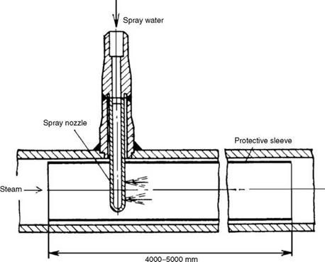
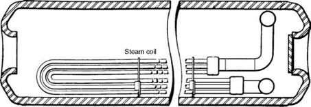
Attemperation is the desuperheating of main or reheat steam to control the final temperatures to the set limits. In a spray attemperator, the principle is a direct contact heat exchange where the feed water (FW) bypasses the ECON and evaporator circuits and joins the superheated steam directly. In a drum attemperator, an indirect heat exchange occurs when the extra heat of steam is dissipated to the drum water.
Besides the temperature control, an attemperator can also control the tube metal temperatures of SH and RH.
Reheater attemperation. Attemperation in RH is only for an emergency condition and not for regular temperature control operation because it reduces the overall cycle efficiency. The spray water added in the attemperator expands only in the IP and the low-pressure (LP) portions of the turbines bypassing the HP section altogether. Spray quantity of 1% steam flow reduces the heat rate by —0.2%. The temperature control of the RH is to be performed by flue gas bypassing or recirculation or by burner tilting.
The attemperator is located at the inlet on the cold reheat line so that the metal temperatures can also be controlled.
Superheater attemperation. Location of the attemperator is important for SH layout.
• Usually in industrial boilers of modest pressure and temperature, it is normal to employ the attemperator at the discharge end of SH when the steam is required at 425°C (800°F) and lower because the tube metal temperatures are low. Sufficient straight distance is necessary between the attemperator and the point of steam usage to ensure that the steam is totally free of water droplets if spray attempera — tion is employed.
• For higher temperatures, interstage attemperation is normal with SH divided into primary and secondary sections. The steam is cooled ahead of its heating in the secondary section, which helps keep the tube metal temperatures low.
• For the same reason many times a two-stage attemperation is adopted when the final temperatures are >520°C with SH divided into three sections, depending on arrangement. The response of the two-stage attemperator is superior to that of the single-stage attemperator.
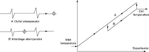
The interstage and outlet stage attemperators are depicted in Figure 6.23. The effect on the metal temperature is easy to infer.
Types of attemperators. The two types are spray and surface.
|
Steam Temperature
FIGURE 6.23 Effect of attemperator location on steam temperature rise. |
|
FIGURE 6.24 Spray attemperator. |
• The required large-diameter piping from SH header to and from the attemperator needed with an interstage device must be very large when the route is made appropriately longer to induce the required flexibility.
• The response is a little slower.
|
Water drum
FIGURE 6.25 Drum attemperator. (From Babcock and Wilcox Company, U. S.A. With permission.) |
Spray attemperators are the only types used in utility boilers.
• They are simple in construction.
• They have practically no steam side pressure drop.
• They are highly responsive.
Surface attemperators, more specifically drum attemperators, have an advantage in low — and medium-pressure process boilers up to —70 bar and are used in bidrum boilers. With widespread improvements in water quality, increased SHOTs, more cogeneration (cogen), and better operator training, attemperators are going out of use mainly due to sluggish temperature control and parasitic water side pressure drop, despite the advantages of freedom from spray-water impurity problems.
Spray water in an attemperator is usually limited to —8% of total flow to reduce thermal shock on steam pipes and ensure that all water droplets get fully vaporized in a short distance. A judicious combination of radiant and convective SHs can achieve a spray water flow as low as 2-3%.
The design should specify 200% attemperation duty to account for several imponderables like variations in fuel quality, effects of slagging and fouling, and maldistribution of gas and steam.
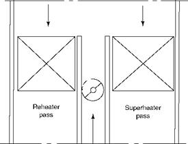
The temperature of the RH steam is regulated when flue gases are passed through a bypass duct between the SH and the RH in two-pass boilers. The arrangement is cheaper but maintenance prone, as the damper extends for the whole width of the boiler and the response is sluggish. This is also used for SH temperature control supplementing attem — peration (Figure 6.26).
Gas Recirculation and Tempering
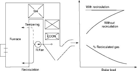
Flue gas from a boiler, ECON, and AH exit at 250-400°C and can be introduced back into the furnace, without interfering with combustion, for altering the heat-absorption pattern. There is an increase in gas quantity without any increase in total heat of gases. Gas can be introduced into the furnace below the CHI gas recirculation (GR) or close to the furnace exit, called gas tempering.
In GR, the cold flue gas mixes with the gas from combustion, resulting in a drop of furnace gas temperature. As the furnace absorption is entirely by radiation, this reduced
|
Flue gas
Bypass Damper |
|
Secondary superheater temperature
FIGURE 6.27 Effect of gas recirculation on secondary superheater outlet temperatures. |
|
FIGURE 6.26 Control by gas bypassing in boiler second pass. |
![]() Temperature leads to a fall in the furnace absorption. Therefore, there is practically no change in FEGT. With higher gas quantity and nearly the same FEGT, all the surfaces downstream experience greater heat absorption due to higher convection. The change is progressively greater toward lower temperatures. Heat from the furnace is thus moved to the convection surfaces. In other words, the heat from the front is moved to the rear (Figure 6.27).
Temperature leads to a fall in the furnace absorption. Therefore, there is practically no change in FEGT. With higher gas quantity and nearly the same FEGT, all the surfaces downstream experience greater heat absorption due to higher convection. The change is progressively greater toward lower temperatures. Heat from the furnace is thus moved to the convection surfaces. In other words, the heat from the front is moved to the rear (Figure 6.27).
In gas tempering, the cold flue gas is admitted into the furnace before the exit after the combustion zone. This results in only a small change in furnace heat absorption but a good reduction in FEGT, as the combustion gas is diluted with the tempering gas. Increased
gas flow and reduced gas temperatures contribute to a reduction in heat absorption in the secondary SH, nearly no change in the RH and some increase in the primary SH, and a good increase in the ECON. Heat is redistributed in the SH downward without much change to the furnace.
The greater the amount of recirculated gases, the greater the redistribution of heat. About 5% is considered as minimum for preventing backflow. Gas recirculation is greater at low loads as the SH and RH temperatures are lower. As the furnace absorption is lowered, GR is also used for controlling the furnace temperatures to regulate metal temperatures and slagging.
Furnace and RH heat absorption remains almost the same regardless of the amount of gas tempering. Its use is more in reducing the secondary SH temperature and fouling in the SH area.
Fans for recycling of gas experience a heavy use in terms of temperature, dust, and the pressure drop. This is an important consideration in evaluating the gas recycling option.
Burner tilt and burner management are the two arrangements available to control the CHI for corner-fired and wall-fired boilers, respectively. In corner-fired boilers, the burner tilt changes the position of the flame ball upward or downward, thereby altering the furnace absorption and FEGT. In wall-fired boilers, a similar effect can be achieved by cutting in and out the lowest and the highest tier of burners.
With tilting of burners, it is not possible to precisely control both SH and RH simultaneously because of the differing characteristics. It is normal, therefore, to control the RH with a burner tilt and the SH with an attemperator.
Slight increases in the excess air give a little more superheat and reheat. The combustion temperature and consequently the furnace heat absorption are both lowered, resulting in slightly higher FEGT and gas weights, which affect the steam temperatures of SH and RH positively. At the same time this method contributes to an efficiency loss due to higher stack loss. For short periods and low loads, this method can be adopted but not on a regular basis at higher loads.


 26 августа, 2013
  admin
admin 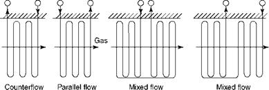

 Опубликовано в рубрике