Water-level indicators (WLIs) or gauge glasses are installed on the boiler drums, deaerator tanks, and CBD tanks on the boiler island. Water-level indicators can be for direct or remote viewing, direct water-level indicator (DWLI) or remote water-level indicator (RWLI), respectively. As per ASME Section 8.5, the most important guidelines for WLI are:
• Each boiler should have at least one DWLI. This is not relevant to once-through (OT) or forced circulation boilers that have no fixed steam and water lines.
• For boilers with maximum allowable working pressure of >400 psia (—28 bar or —3 MPa), two DWLIs are to be provided. Alternately, there can be one DWLI and two independent RWLIs.
• When two independent RWLIs are installed and are operating reliably, one DWLI may be shut off but kept in a serviceable condition.
• The lowest visible water level in a DWLI and an RWLI should be at least 50 mm above the lowest permissible water level. (This is usually upper end of the last downcomer tube.)
Boiler codes differ slightly in specifying WLIs, although the underlying principles are the same. Respective codes must be studied carefully before adopting the WLIs in any application.
Achieving drum water level indication is not particularly easy. With relatively small diameter drums used in modern high-capacity boilers, more accuracy is needed. The high pressures and temperatures in the drums, coupled with fluctuations, make the drum water level measurement much more difficult than in other containers such as tanks and silos. Direct and remote WLIs are the two broad classifications of gauge glasses.
Several types of WLIs are available.
Direct water-level indicators are available in several designs. In small boilers with steam drum levels of up to 20 m from the operating floor, the drum water can be seen adequately with suitably illuminated reflex or bicolor WLIs. For a better viewing from a wider area, the level can be seen by providing a suitable enclosure and a pair of reflecting mirrors, called the telescopic arrangement. For bigger boilers with steam drums located at 50 m and above the operating floor, the DWLIs are too remote even for reflecting in mirrors.
Direct WLIs suffer from displaying a lower level than the actual level due to the density difference of water between the drum and the (thin) cooled water column of the DWLI. Typically, at 180 bar drum pressure, the level at the top of 200 mm water column displayed in the gauge can be lower than the actual by as much as 120 mm, depending on the ambient condition. Despite this disadvantage, the comfort it induces cannot be replicated by watching the level of an RWLI; hence, it remains as a reliable backup for RWLI.
These glasses are the oldest and the simplest of the DWLIs employed for nontoxic and nonhazardous media and low pressures up to 15 barg (—220 psig). The gauge glasses are supported at their ends and are subject to bending which limits their use to low pressures. Also, the affinity of alkaline drum water to glass increases with the temperature (and consequently the steam pressure) and does not permit the use of plain glass beyond the low pressure. The breakage of gauge glass can be dangerous to the operators as the splinters can fly around. With clear water, the meniscus is visible only by the vibration of the column. A glass protector is usually used to improve the safety and visibility. Closed on three sides, the protector is a metal sheet with a thin black strip at the center, which gets magnified by the lens effect of water to improve the display. Figure 8.66 shows the tubular gauge glasses with and without the protector sheet. The plain gauge glasses are rarely used as they do not satisfy the safety and display requirements.
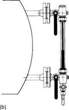
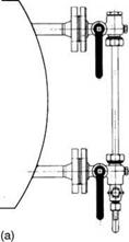
|
FIGURE 8.66 Tubular gauge glasses: (a) plain and (b) protected (up to ~15 bar). |
![]()
|
Water Space |
![]()
|
Sealing gasket Sight glass Cushion gasket Body |


|
Steam Space |
![]()
|
Light ray |
![]()
|
Light ray |
![]() FIGURE 8.67
FIGURE 8.67
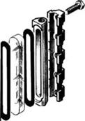
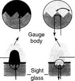
Reflex-type gauge glass (up to —32 bar).
These glasses are employed up to a pressure of —32 bar. The flat glasses are plain on the outside and serrated on the inside where there is contact with water. Owing to the difference in the refractive indices of steam and water, the incident light rays suffer reflection in steam space and not in water space as they try to pass through the 45° slanted surfaces of the corrugation as shown in Figure 8.67. The steam space appears as silver white on the transparent water space.
The affinity of water to glass is shown in Figure 8.68. The sight glasses in a gauge glass are subjected to mechanical and chemical forces. Chemical attack is determined by the alkalinity (pH value) and temperature (hence the pressure). More importantly, the condensation
|
|
PH
FIGURE 8.68
Affinity of water to glass.
Of steam and its continuous running down on the glass create a constant abrasion, making the glass dull, obscuring the view and calling for replacement. In an unprotected glass, the steam pressure and alkalinity of water should be limited to 35 bar and 10 pH for the best economic life. For higher-pressure application, the glasses are protected with high — quality transparent mica sheet, which prevents contact of water with glass. The mica can be provided only for highly polished flat glass and not on a serrated surface of reflex glass. Reflex-type DWLIs are restricted for use up to —32 bar. The glasses must be clear with no inclusions, should be thick (20-30 mm), and made of borosilicate to withstand use. They are heated, quenched, and tempered to case harden the top 3-5 mm layer and polished a high finish to offer a good view of the water level. In a bull’s eye DWLI, the small glass plates are made of aluminosilicate to offer a better life. Glass plates are vital parts of gauge glasses, and require periodic replacement.
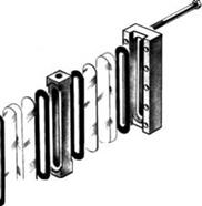
Transparent gauges can be used up to 120 bar with a viewing distance of —20 m at a certain angle. The water space is contained between two flat glasses shielded with mica sheets to withstand high pressure and illuminated at an angle from the rear. The light rays impinging on the water meniscus are reflected and therefore the viewer sees the water level in the illuminated gauge (Figure 8.69).
|
Transparent glass Cushion joint |
|
A Du: Cover plate |
|
Mica shield Center piece Sealing gasket |
|
|||||||||||||||||||||||||
 |
|||||||||||||||||||||||||
|

|
II |
> |
|
|
|0 0 |
||
|
* О |
||
|
T $ |
H |
|
Red^ |
|
Green |
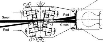
FIGURE 8.70
Bicolor gauge and action (up to 180 bar).
Bicolor gauges are built for pressures up to 180 bar. They are similar to transparent gauges but have wedge-shaped glasses to provide a differential expansion to light in steam and water spaces. There is an illuminator located at the rear side of the gauge with two color slides fixed in front of it—red and green. Seen from the front, red is to the left. Red light passes through the steam space and gets deflected sideways in water space and vice versa. The gauge needs to be mounted vertically and a set of mirrors are needed for remote viewing (Figure 8.70).
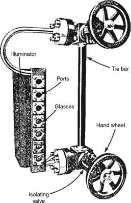
These gauges are also called bull’s eye types. They employ bicolor action with port-type glasses. These glasses are —20 mm 0 and are held in thick-AS bodies to withstand higher pressure than possible with flat glasses. They are suitable up to —220 barg (—3200 psig) (Figure 8.71).
|
FIGURE 8.71 Port-type bicolor gauge (up to —220 bar). (From Tyco Flow Controls, U. S.A. With permission.) |
Multiple gauge glasses are employed for viewing level in larger vessels such as deaerators (Figure 8.72).
Remote water-level indicators are of manometric and electronic, types with the latter becoming more common.
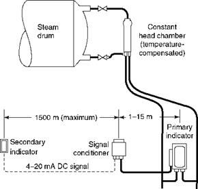
These are simple, reliable, and inexpensive. Small changes in differential pressure caused by changes in the pressure head compared with a fixed column of reference can be transmitted to a pointer linked to a scale or to a remote indicator by means of an electronic or pneumatic transmission. The reference leg reading, which is subject to the density errors similar to the DWLIs, is compensated with a pressure-sensitive coil in the pneumatic version and a pressure transducer in the electronic version. Load changes cause swell or shrinkage to the water level, affecting the reference water column. A pressure and temperature compensation is necessary to correct the reading. The limitations of the manometric gauges are their slow response and difficulty in ensuring that the reference column is full (Figure 8.73).
|
|
<$) |
|
Uninterrupted sight length |
 |
|||||||||||||
|
|||||||||||||
|
Combined sight length |
![]()
|
Single sight length |
![]() FIGURE 8.72
FIGURE 8.72
Gauge glass combinations.
|
FIGURE 8.73 Schematic diagram of manometric gauge. (From Tyco Flow Controls, U. S.A. With permission.) |
|
FIGURE 8.74 Schematic diagram of electronic remote water-level indicators along with probe. (From Tyco Flow Controls, U. S.A. With permission.) |
Electronic Gauges
The most common types are conductivity electronic gauges. They work on the principle of conductivity of water exceeding that of steam. A probe vessel is mounted on the steam drum with several probes vertically at regular intervals. As the water level rises, the submerging probes make contact and complete the electrical circuits in sequence, lighting up indicating bulbs at the other end of an indicator. The added advantage of an electronic gauge is that at predetermined water levels, it can actuate fuel cutoff interlocks and alarms, which energize solenoid valves or motors controlling pumps. The probes are the most important components of the system. Figure 8.74 shows an electronic-type RWLI and conductivity probe.
Further Readings
ASME BPVC Section I for safety valves, WLIs and other boiler mountings.
Handbook of Fans, Buffalo Forge.
Makansi, J., 1986, Special report on particulate control: optimising precipitators and fabric filters for today’s power plants, Power, December.
O’keefe, W., 1983, Special report on valves, Power, February.
O’keefe, W., 1984, Benefit from systems approach with today’s safety valves, Power, January.
Power Plant Engineering, 1996, Black and Veatch.
Reason, J., 1983, Special report on fans, Power, September.
Special report on controlling particulate emissions, 1980, Power, June.
Weimar, P., 1980, Extend fan life with high performance materials that resist vibration/corrosion, Power, December.


 31 августа, 2013
  admin
admin 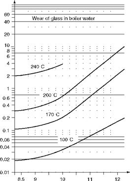

 Опубликовано в рубрике