Boiler and evaporator surfaces are the HSs that are exposed to the flue gases on the outside and carry the steam and boiling water mixture on the inside.
The furnace is the enclosure around the firing equipment, which provides adequate
1. Volume to permit completion of combustion, that is, to meet the residence time requirement to burn the fuel
2. Surfaces to cool the gases to an acceptable level to enter the downstream surface, usually the SH, without the fear of ash deposits or tube overheating
Furnace volume is the volume of the open chamber that surrounds the firing equipment and extends from the top of stoker, bed, ash pit, or floor to the exit plane at which the next surface (usually SH or screen) starts. Platens are always placed within the furnace.
Heat transfer in a furnace chamber is almost entirely by radiation. Projected radiant surface (PRS) of the furnace is the HS that participates in cooling the flue gases. It comprises all areas of the walls of the furnace enclosure including the area of the exit plane. Areas of both sides of platens, wing walls, and division walls are also added. Effective PRS (EPRS) is the adjusted PRS that takes into account the fuel, types of walls (membrane, tangent, spaced, etc.), extent of refractory covering on walls, effect of possible slagging, etc. Furnace exit gas temperature (FEGT) is calculated with the help of EPRS as elaborated in Section 6.2.I.2.
The firing device is a grate, combustor, bed, or burner. The dimensions of the firing equipment and flames primarily govern the plan area and shape of the furnace. Necessary clearances have to be provided for burners to avoid flame impingement, which can lead to overheating and wastage of tubes. The furnace height is decided by the furnace volume or residence time requirement of individual fuel and the type of firing equipment. Table 6.1 provides a guide for residence times. Residence time is required for a fuel particle to reach the midpoint of the furnace exit aperture from the firing equipment (center of heat input, to be precise), assuming the whole furnace to be at the isothermal
|
TABLE 6.1 Range of Furnace Residence Times (in Seconds) for Various Fuels
|
Temperature of FEGT. In package boilers with horizontal gas flow, the burners decide the cross section and the residence time whereas the flame length governs the length of the furnace.
The furnace experiences the highest gas temperature within a boiler. To extract the high heat levels required, evaporator surfaces are used in furnaces because of the extremely high boiling heat transfer rates. Gas cooling and tube metal cooling are the most effective methods. Plain carbon steel (CS) tubes are used in construction where departure from nucleate boiling (DNB) is not a possibility and tube metal temperatures rarely exceed 50°C over saturation. Since no evaporation occurs in SC boilers, cooling is not very effective and water temperatures approach critical level (374°C), thus requiring low alloy tubes in the furnace.
Furnace Exit-Gas Temperature or Furnace Outlet Temperature (FEGT or FOT)
Furnace exit-gas temperature or furnace outlet temperature is the average gas temperature at the middle of the furnace exit plane. Heat transfer in the furnace is mainly achieved by radiation. The exception is the furnace of circulating fluidized bed combustion (CFBC) boilers, which has a thick layer of hot ash falling down along the tube walls and transferring its heat primarily by conduction and convection. High furnace gas temperatures and relatively cool furnace tubes provide very good heat-transfer rates. But the furnace surface is limited, which makes the cooling of flue gases more expensive in the furnace than on other surfaces. The furnace cooling is therefore restricted only to the extent of achieving a temperature just low enough to introduce other types of surfaces. The FEGT then translates to the initial ash deformation temperature (iAdT) of —100°C as a margin of safety.
An accurate estimation of FEGT is not possible by theoretical calculations alone because several variables keep changing in a furnace with not-so-simple geometry. The size and the number of flames, emissivities, flame temperatures, and cleanliness of furnace are all subject to constant change. The practical adjusted surface (AS) or EPRS method, is proprietary to each boilermaker, evolved over time and fuel — and geometry-specific. The calculations involve the following steps:
• Calculate PRS of the lower furnace up to the open pass (below platens) and total furnace up to the furnace exit.
• Derive EPRS from projected surface by multiplying with effectiveness factors for each wall. Effectiveness factor varies from 0.9 to 0.98 for membrane walls depending on the fuel and the slope of the wall.
• Calculate the heat released and available (HR and A) from the fuel and air. The total available heat, based on fuel net calorific value (NCV), including the heat addition in AH, is adjusted for the possible unburnt carbon loss and furnace radiation losses (assumed to be half of the total). Ambient temperature is taken as the datum to calculate this heat.
|
Ha) — if |
|
(NCV |
|
-‘ub |
|
H0 = total heat released and available = fuel fired |
|
|
Where
R = radiation loss Ha, = heat added to air Lub, = unburnt loss
• Calculate the heat release rate
H
Heat release rate =—————— — (6.2)
EPRS
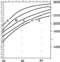
From the proprietary graphs, the FEGTs are read for each fuel and type of firing (grate or burner). The FEGT so obtained is accurate only to the extent of approximately ±50°C. A typical graph for burner and grate firing is given in Figure 6.1.
• Burner firing results in a higher FEGT because the center of heat input (CHI) is higher.
• Fuels with higher volatile matter (VM) release more heat at a higher level compared with fuels with less VM, although both are grate fired and consequently give higher FEGT despite their higher moisture.
The FEGTs for lower furnace at open pass plane (T1) and total furnace at exit (T2 or FEGT) are read from the same graph to calculate the radiation falling on the SH. H1-H2 is the heat absorbed in the open pass in front of the SH and the platens. Dividing by the EPRS of each wall and platens, heat flux can be estimated along with heat incident on the SH or screen at the furnace exit plane. Correct estimation of the radiant heat falling on SH at the furnace exit is very important for its proper sizing. The boilermakers have such graphs for each fuel for several moistures and VMs.
For fluidized bed combustion (FBC) boilers, the calculations are done in a different way. Heat balance over the bed gives the bed temperature and the heat balance of the free board
|
1000 Btu/ft2 50 90 130 170 |
![]()
|
1400 |
![]()
|
1200 |
![]()
|
1000 |
![]()
|
800 |
![]()
|
600 |
![]()
|
1000 kcal/m2 Furnace heat release |
![]()
|
2 Z5 « CD Ј CD |
![]()
|
FIGURE 6.1 Typical FEGT versus heat release graph for burner and grate firing. |
![]()
|
O |
![]() A: Coal—pulverized fuel fired B: Natural gas—burner fired C: Oil—burner fired
A: Coal—pulverized fuel fired B: Natural gas—burner fired C: Oil—burner fired
D: Bagasse—grate fired E: Coal—grate fired
Gives the exit temperature. There is a staged combustion, and the walls are covered with ash whose effects have to be accounted for.
As the boilers grow in size, the furnace volume increases cubically whereas surface increases by squares, leading to a mismatch—there is more volume than surface. Division walls are introduced to correct this mismatch. A division wall is an evaporator wall in the middle of the furnace, usually from bottom to top, receiving heat from both sides. Wing walls and platen SH introduced in the furnace for picking up heat economically also help to correct volume-to-area ratio.
Modern boilers employ fully water-cooled surfaces as furnace enclosure walls, with little or no refractory that calls for costly downtime and maintenance, unless there is a specific requirement for
• Erosion protection of tube walls such as in stoker firing up to 2 m or bubbling flu — idized bed combustion (BFBC) boilers around the bed
• Corrosion protection as in lower combustor of CFBC boilers
• Overheat prevention like the furnace floor of oil — and gas-fired boilers
It has taken several decades to progress from full brick wall construction to full water wall cooling—tube and tile (Figure 6.2a), and bailey wall construction, etc., paralleling the advancements in combustion. The tangent walls (Figure 6.2b), with tubes touching each other, were major advancements in the early 1950s, but the following were the two major issues to be addressed:
1. Construction time increased because each tube was to be lifted into position.
2. Tube repair was difficult because the affected tubes had to be jacked out of position.
Membrane panels (Figures 6.2c and 6.3), with a steel strip/bar inserted between the tubes and shop welded on submerged arc welding machines (to give adequate weld penetration between the bar and the tube) and finish fabricated in transportable panels remedied the situation and made tangent tube construction almost obsolete. With the end headers fitted and heat treatment carried out in the fabrication shops, the site work was considerably simplified.
The advantages of the membrane walls over tangent tubes can be summarized as follows:
• Faster and easier site erection facilitates very large boilers.
• Tube repair is much simpler.
• Fit and finish of shop-made panels is far superior.
• Capacity to withstand furnace puffs is better because the membrane panels behave like plates.
• For the same EPRS, membrane panels use fewer tubes.
• Tube diameters are smaller, saving pressure part (PP) weight.
|
FIGURE 6.2 (a) Tube and tile construction. (b) Tangent tube construction. (c) Membrane wall construction. |
The membrane strip is usually 6-8 mm in thickness and varies from 12 to 60 mm depending on the furnace heat flux. Only high heat flux, such as in pulverized fuel (PF) boilers and package boilers for oil and gas, strictly calls for 8 mm thick strips.
• For PF boilers with high heat flux, the width of the membrane strip varies from 6 mm to a maximum of 18 mm.
• For highly rated package boilers, the width is often 12 mm.
• For FBC boilers, with relatively low heat flux, the width can be as high as 60 mm.
• Waste fuel and waste heat boilers also use wide strips.
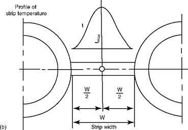
The maximum temperature attained by the strip at its midpoint and the stress levels generated govern the strip width which, in turn, is dependent on the heat flux (Figure 6.3b).
Panel welding and panel bending (vertical or horizontal) machines are expensive and occupy considerable shop space. Some small boilermakers therefore employ hand welding using straight and bent tubes as required. Is hand welding a substitute for machine welding? The answer is perhaps not. IW machine welding and strip bonding are strong and the weld deposit is large, which provides a large base of metal to transfer the heat of the
|
I i
|
|
FIGURE 6.3 (a) Membrane panel. (b) Temperature variation in membrane strip. |
Membrane to the tube. The resulting temperature gradient profile is gentler and stresses developed are lower. The hand welding leaves a much smaller weld deposit. For low heat fluxes, such as those encountered in FBC and biofuel systems, firing hand-welded panels yield good service at a very low cost, despite the obvious disadvantages of lower speed of production and inferior weld penetration that account for poorer transfer of heat from gases to water.
Several areas of construction of furnaces demand lining with refractory, mainly for erosion, corrosion, and overheat protection.
• Staged combustion demands refractory facing in the lower part of the furnace, below the secondary air (SA) nozzles, to protect the tubes from corrosion due to the prevailing reducing conditions, typically in CFBC and black liquor (BL) recovery boilers.
• In BFBC boilers, the furnace tubes around the bed, for a height of —1.5 m, need protection against erosion due to the constant impingement of bed material.
• In spreader stokers (SS)-fired boilers a stream of coal lumps hits the rear and side walls as the spreaders hurl the fuel into the furnace, causing tube erosion up to a height of —1.5 m.
• In BL recovery boilers, the lower furnace needs a defense against corrosion due to reducing atmosphere and erosion because of the continuous flow of the smelt on the tube walls.
• In cases of excessively low GCV of fuel, the lower/front end of the furnace is sometimes refractory-lined to hold the heat and re-radiate, such as for firing blast furnace gas (BFG) in package boilers.
• Stoker arches are good examples of refractory lining absorbing heat and re — radiating on green fuel for ignition.
• All burner openings in PF boilers and many oil — and gas-fired boilers need protection against tube erosion due to high-speed gas streams.
• In package boilers, the furnace floor is exposed to radiant heat. With steam blanketing the upper part of the tube, there is insufficient cooling. Suitable lining is needed to protect the tube from overheating.
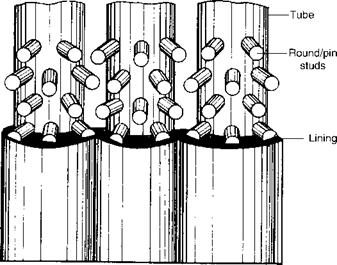
Many such applications are handled in modern furnaces by gun studding the tubes to hold the appropriate refractory lining. Studding needs have to be carefully evolved. Different arrangements are developed for different requirements.
• Pin studs are usually between 8 and 12 mm in diameter and 15-25 mm long, welded to tubes on a triangular pitch (Figure 6.4).
• They can be made of CS or stainless steel (ss), depending on the temperature of the stud and the corrosion environment. Stainless steel is more common.
• Studs conduct the heat of the refractory lining to the tube and keep the lining cool. Hence the studs are tapered at the base and heavy duty pressure welding is used so that the base of the stud and the surfaces of the tubes melt and adhere. The strength of the weld is established by the bending of stud in a hammer test. The intent is to provide a strong weld that passes the heat received from the flame and lining to the tube effectively.
• The stud temperature increases toward the tip. The maximum length of the stud should be restricted to the temperature limit of the material.
• The refractory can be Al2O3, PCO, SiC, or any such castable as required. SiC is the most conductive, dense, and expensive of all the linings. Circulating fluidized bed combustion boilers usually employ linings to transfer the heat as well as to withstand erosion. Al2O3 lining is used where heat transfer is less important than erosion resistance. PCO is popular in BL recovery boilers.
For large boilers with sizable studding, dedicated gun studding machines and teams of workmen are needed. But for small boilers and sporadic requirements, CS or Y-shaped ss plate studs are hand-welded and then refractory mixture is applied.
The considerations in tube size selection are:
• Tube diameters used in modern furnaces vary from 38.1 mm (1.5 in.) to 76.2 mm (3 in.) OD.
|
|
FIGURE 6.4
Typical studded tube.
• Smaller diameter results in a thinner tube, which has an improved thermal flexibility but is mechanically weaker and offers greater inside friction loss. If there is an adequate thermosyphonic head to compensate, smaller tubes are preferred because they are lighter and hence cheaper so long as they can withstand the mechanical requirements.
• Tall furnaces of utility boilers with natural circulation usually adopt larger- diameter tubes—63.5 or 76.2 mm (2.5 or 3 in.) OD. With assisted and forced circulation, tube sizes can be reduced to 50.8 and 63.5 mm (2 or 2.5 in.) OD tubes.
• Package boilers tend to use 38.1-50.8 mm OD. With water quality in boilers vastly improved, the need for conservative diameters no longer exists.
• For heat transfer, the tube diameter does not have great significance. For circulation, larger tubes are better because they offer less resistance. Mechanical stability is very important in the selection of tube size.
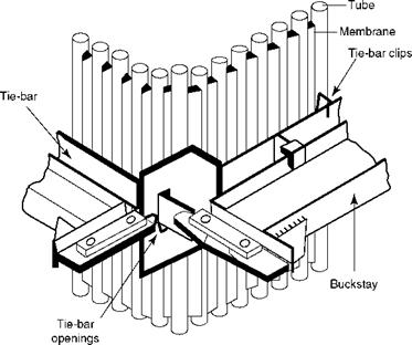
Buckstays are provided approximately every 2-3 m along the furnace height to hold the furnace in proper shape against internal gas pressures. A buckstay is an assembly of four girders supported on all the four walls and hinged at the corners to provide for expansion. The rise in internal pressure beyond the safe limit allows the gases to escape from the corners without damaging the tubes (Figure 6.5).
Usually furnaces are designed for internal pressure fluctuations of ±200 mm wg. In case of large boilers with heavy back-end and cleanup systems, high draft-induced draft (ID) fans are used. In a flame-out situation, from sudden termination of fuel supply (oil valve closing too suddenly or a master fuel trip), the furnace experiences a sudden decay in pressure. Maloperation of dampers can also create a similar situation, called implosion. Then the furnace setting is designed for ±500 mm wg.
|
|
FIGURE 6.5
Typical buckstay details.
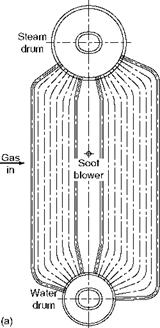
Furnace and BB are the two evaporator surfaces in a boiler. Normally, a furnace is a totally radiant surface, whereas a BB is fully convective. A boiler bank is a large surface made up of tubes fully expanded between top/steam and bottom/water drums. Until the 1950s, when the steam pressures were low and the coals were better, the BBs were the largest surfaces with three or four drums. Today bidrum boilers form the bulk of industrial boilers (Figure 6.6). The limit for the bidrum design is 100-120 bar. Boiler banks are absent in the radiant single-drum boilers.
A boiler bank provides a substantial portion of the water-holding capacity. With large amounts of saturated water, the BB serves as a big reservoir of heat. No doubt, it retards the boiler start-up and shutdown, making the response a bit sluggish; and it also makes a boiler very forgiving for operational deficiencies. Improvements in water quality and instrumentation have increased the customer expectation for superior boiler response from conventional fuels, calling for single-drum boilers with steaming ECONs (if required), particularly for pressures >60 bar. For high-moisture fuels such as wood, bagasse, BL, where there is a lot of heat in the water vapor of the flue gas, a BB is indispensable because ECON alone is insufficient to extract the required amount of heat, particularly in medium pressures.
No radiant heat is usually incident on the BB surface, and heat transfer is purely convective with some intertube nonluminous radiation. It is governed by the gas-side heat transfer coefficient because the water-side coefficient is too high.
From the heat balance of the bank, the heat gained by water is equal to the heat lost by the flue gases, which is stated as
|
(6.3) |
![]() R X A X LMTD = Wg X Cg X (T — T2)
R X A X LMTD = Wg X Cg X (T — T2)
|
|
|
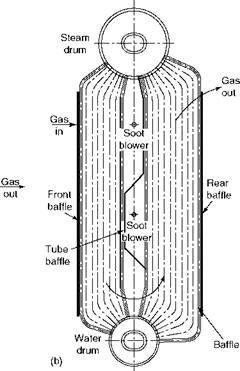
FIGURE 6.6 (a) Single-pass boiler bank in cross flow. (b) Two-pass boiler bank in longitudinal flow. |
 Where
Where
|
LMTD = the log mean temperature difference = |
 R = overall gas-side heat-transfer coefficient, both convection and radiation A = HS of the tubes measured on the OD
|
Loge |
![]() Ti -1
Ti -1
T2 — t
|
W„ |
![]()
|
C |
![]()
|
Ti — T2 |
![]() Weight of the gas specific heat of the flue gas gas temperature drop
Weight of the gas specific heat of the flue gas gas temperature drop
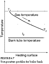
In a BB, the amount of HS is known because of the predetermined configuration. BB exit-gas temperature (BEGT) can be found using Equation 6.3. For single-pass BBs, the T2 — t is in the range of 120-150°C, whereas for two-pass BBs, it is ~100°C for coal-fired boilers (Figure 6.7).
6.2.2.1 Tube Expansion in Boiler Bank
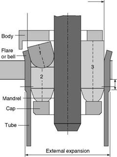
The tubes are held in the tube holes in the drums by means of mechanical expanders (Figure 6.8).
• The tube is expanded by force to fill the tube hole, and by friction the two are held together. Normally, a straight distance of at least 20 mm is needed for friction gripping of the tube. Hence, the minimum plate thickness is 20 mm.
• Bell mouthing, to arrest any possible axial movement, follows the expansion of tubes.
|
|
|
■ ID after expanding — (Tube ID + 10%) |
|
Tube Expander |
|
Protrusion inside drum = 8-10 mm |
|
Drum plate Tube expansion beyond plate = minimum 12 mm Rolls 1. Bell 2. Short 3. Long |
|
Tube OD + 1-1.5 mm |
|
FIGURE 6.8 Tube expander. |
•
|
FIGURE 6.7 Temperature profiles for boiler bank. |
 It is normal to provide one or maximum two grooves in the tube hole for the tube material to flow into the drum plate and lock itself to prevent loosening during transportation to site.
• On the inside of the drum, the tubes must protrude by —12 mm and the tube holes should have a clearance of 12 mm (to allow for bell mouthing).
• On the outside of the drum, the tubes should be expanded by at least 12 mm.
• Beyond 80-100 bar design pressure, it is normal to seal weld the tubes to the inside of the drum.
• A pressure of 100 bar and at times even 120 bar for some manufacturers, is the maximum limit for tube expansion, as the drums attain a thickness of 150 mm or more, making it difficult to expand the tubes for such a length.
The salient points of BB tubes can be listed as follows:
1. Tube size
A. Tubes employed in the BB range from 38.1 mm (1.5 in.) to 63.5 mm (2.5 in.) OD.
B. Smaller tubes are better for heat transfer and larger tubes for mechanical loading.
C. With improved water quality the bias against smaller tubes of <50.8 mm (2 in.) OD has slowly disappeared, as has the frequent cleaning requirement of the boiler tube internals.
D. Tubes with 38.1 mm (1.5 in.) OD are mostly found in package boilers.
E. Bottom-supported modular designs for oil — and gas-fired boilers usually adopt
63.5 mm (2.5 in.) tubes.
F. The most common size of tubes is 50.8 mm (2 in.) OD.
2. Tube material
A. Since the BB contains only saturated water, the metal temperatures scarcely exceed 350°C for which CS is the most appropriate material.
B. Low CS with lower hardness is preferred because the tube expansion is a cold working operation that needs a soft and ductile material, at least over the length that is expanded.
C. Electric resistance-welded (ERW) tubes are preferable to seamless, as the concentricity of the bore to the OD is automatically ensured, which on expansion, would cause no unevenness of material flow. This requirement of tube concentricity applies to thicker tubes at higher pressures. But the fear of opening along the weld line is also strong, although the ERW tube-making process is improved.
3. Tube spacing
A. Clear spacing between tubes is governed by the permissible gas velocities, fouling tendencies, and access requirements.
B. In-line tube arrangement is adopted for accessing the inside tubes of the bank and for combating the erosive forces of the dust-laden gases. It is usual to alternate the pitch along the drum length to gain an access space of 60 mm after every other tube, for insertion of a hand. Instead of choosing a uniform 100 mm pitch, an alternate pitch of 110 and 90 mm is chosen.
C. With clean gases staggered, pitching is common to achieve better heat transfer.
Boiler Bank Types and Design Features
Based on the flue gas flow the BBs types are:
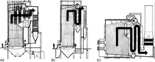
• Single-pass cross flow (Figures 6.6a and 6.9a) or multipass cross flow
• Multipass longitudinal flow (Figures 6.6b, 6.9b, and 6.9c)
Salient points are as follows:
• For dust-laden gases, the erosion considerations favor the use of single-pass banks,
Although the heat transfer is lower.
• Layout issues decide between cross flow and longitudinal flow for cleaner gases.
• In most BBs the gas flow is verticle, except in some package boilers where it is horizontal and the gases are necessarily clean.
• A BB usually consists of, along the circumference of the drum,
• 18-22 tubes allowing longitudinal and cross flow of gases, which are normal to the drum axis
• 10-12 tubes allowing horizontal flow of gases, which are along the drum axis
|
FIGURE 6.9 (a) Single-pass cross flow, (b) two-pass longitudinal flow, and (c) multipass longitudinal flow boiler banks. |
• In the tube bank, one-third of tubes on the colder side, circumferentially in the case of cross flow or axially in the case of horizontal gas flow, are made into down — comers by suitable baffling inside the drum.
• A minimum centerline distance between drums has to be maintained for a satisfactory circulation to induce the required thermosyphonic head.
— With high heat flux prevailing in package boilers, 3 m height is possible.
— In bidrum boilers, a minimum of 4 m is required.
The maximum height is dictated by boiler arrangement. In the bottom-supported oil and gas bidrum boilers, heights of 12 m are common. In such tall bottom-supported banks, tube diameters are seldom <50.8 mm (2 in.) OD. Adequate measures for vibration prevention have to be taken.
• A BB should preferably cool the flue gases to at least 450°C to
— Avoid flow reversal in the downcomer tubes due to steam generation
— Permit CS ducting as at >450°C ss or CS ducting with brick lining
• This requirement is at times difficult to meet in single-pass boilers. The solution is to check the circulation calculations carefully for steam quality in the downcom — ers. Unheated downcomers can resolve the situation.
• Soot blowers (SBs) are provided in the bank for cleaning the tubes. Rotary blowers are adequate as the gas temperatures are low. It is usual to adopt blowers from one side for boiler widths of 7 m maximum. The depth along gas flow is usually limited to —1.5 m, which is within the cleaning radii of rotary blowers for most fuels with normal fouling tendencies.
• Drum thicknesses can be reduced by using bank tubes with swaged tube ends. Swaging is a cold forming process of reduction of diameter by either roll forging or end squeezing. This is followed by annealing to remove the stresses of the cold working and to induce the softness and ductility required during tube expansion operation. Swaging is normally limited to 25% (63.5-50.8 mm). Since the circulation is very vigorous in the BB, swaging has no adverse effect and is freely used even for high pressures (HPs).


 26 августа, 2013
  admin
admin 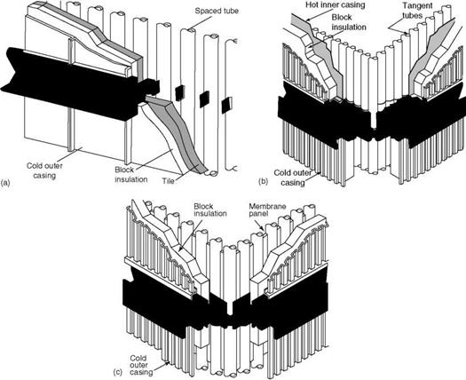

 Опубликовано в рубрике