Fans are perhaps the most important of all the auxiliaries because they affect the boiler
• Performance
• Auxiliary power consumption
• Dynamics
Almost all boilers are provided with fans for air and flue gas movement, except for certain waste heat recovery boilers (WHRBs) and heat recovery steam generators (HRSGs), which receive pressurized gas from the process plants or gas turbines (GTs).
• Balanced draft boilers employ a pair of fans, one for forcing the airflow through the firing equipment and the other for inducing the gas flow up to the stack, thus balancing the forced draft (FD) and the induced draft (ID) to achieve balanced draft. This pair is a single set of fans in smaller boilers and double set of fans in larger boilers.
• Pressurized fired boilers have only a single FD fan arrangement to push the air all the way to the chimney. In larger boilers, a double set of fans is employed.
• There are other fans, such as the secondary air (SA) fans, mill fans, and so on, depending on the boiler process.
• Fans provide air for combustion and removal of flue gases in line with the load requirement.
• Fans maintain the boiler draft.
• Auxiliary power consumption of a boiler is substantially contributed by the fans, necessitating efficient fans for new boilers and ways to optimize fan power in running boilers.
• Boiler dynamics are largely governed by the fans, as their inertia is high due to their large and heavy impellers.
The fan assemblies and drives constitute the largest and the most critical part of the boiler auxiliaries.
• A fan can be defined as a volumetric device, that moves air or gas from one place to another, overcoming the resistance to flow.
• Fans overcome static forces. Total pressure, however, includes velocity head, which is due to kinetic energy. Figure 8.1 describes pressures.
• As a volumetric device, a fan gives output in cubic meters and generates head in millimeters water gauge and not in kilograms and millibars. The weight and pressure are the derived figures, depending on the density or specific volume. Therefore, fluid density, which, in turn, is affected by temperature and altitude, has an overwhelming effect on the fan performance.
• The behavior of any fan is captured by its characteristics, which are a set of graphs drawn against a common x-axis of fan volumetric output Q. Head (H), efficiency, and shaft power are the three variables plotted against Q. The characteristics of various types of fans are given in Sections 8.2.4 and 8.2.5.
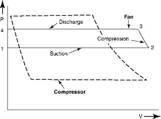
Fans, blowers, and compressors all move air and gas, but the pressure ranges differ.
Fans work from a few millimeters to —2000 mm wg (~1 psig) but handle more volume.
|
Static and total pressures. (From Power magazine. With permission.) |
|
FIGURE 8.2 Fan and compressor cycles on P-V diagram. |
Blowers go up to 2 barg, whereas compressors start from 2.5 barg. Figure 8.2 shows this point.
There are three types of fans; each fan is different in terms of capacity and pressure generated, degree of control, resistance to wear, and corrosion. Centrifugal fans move air and gas
Perpendicular to the fan shaft, whereas axial and propeller fans move them along the fan shaft (Figures 8.3 through 8.5).
1.
|
Casing |
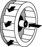
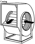 Centrifugal fans operate by forcing the air to rotate in the fan housing. The resultant centrifugal force develops the pressure to move the air stream. Most fans in the boiler are of centrifugal type in which the fluid accelerates from the root to the tip of the blade perpendicular to the fan shaft and collects in the scroll casing.
|
Impeller
Flow |
FIGURE 8.3
Centrifugal fans.
|
|
FIGURE 8.4
Propeller fan.
|
|
FIGURE 8.5
Tube and vane axial fans.
2. Propeller fans move large amounts of air by striking at an angle and developing small heads. The housing plays little role. The flow control is minimal. Boiler ventilation room exhaust and ID cooling tower fans fall in this category.
3. Axial fans are essentially propeller fans with proper housings that provide a definite control, sometimes better than that obtained with centrifugal fans. The fluid accelerates parallel to the fan shaft.
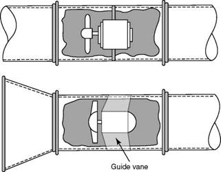
Vane axials have guide vanes before or after the wheel to streamline the flow. Large axial fans are used for the main combustion air for their efficiency and control.
Tube axials have no guide vanes.
All fans contain two parts: static and dynamic in the form of casing and rotor/impeller assemblies, respectively. Impellers, due to rotation, impart energy to air or gas for moving against a set pressure, whereas the casing collects and guides the fluid.
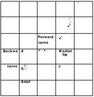
Centrifugal fans are divided on the basis of the shape of the blades used in the impeller. Different shapes impart different characteristics. There are three types of blades:
1. Backward curved or backward bladed
2. Radial
3. Forward curved or forward bladed
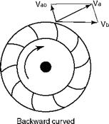
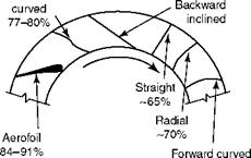
In addition, there are variations to these basic shapes for specific duties. Forward blading imparts a greater absolute velocity to air due to the shape of blading as compared to backward blading for the same tip speed. For this reason, the backward-bladed fans can operate at a higher tip speed than the forward-bladed fans (Figures 8.6 and 8.7).
|
|
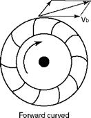 FIGURE 8.6
Air velocity profiles.
|
Backward
72-75% |
FIGURE 8.7
Various blade shapes and static efficiencies.
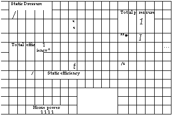
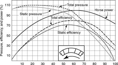
The backward-curved fans, which are also called the single-thickness aerofoils, have the advantage of self-limiting or nonoverloading power characteristics as depicted in Figure 8.8. The fan efficiencies are higher, between 77 and 80%. Because higher speeds are needed to generate the required head, the particulate matter in gas streams can cause erosion of the impellers of ID fans if the dust is aggressive. With improved gas-cleaning equipment, this is not a serious issue. Backward-curved fans are extensively used in boilers for FD, PA, and ID fans.
Backward-inclined blading, unlike backward-curved blading, is not favored due to its unstable characteristics.
Backward-curved aerofoil blading is more efficient, 84-91°%, with lower noise levels. This type is more expensive to make and repair, good for cleaning applications, and popular for utility boilers.
Radial-bladed fans run at a lower speed in comparison with the backward-bladed fans, which makes them preferred for high dust loading in gases. As shown in Figure 8.9, the efficiency is low, at —70%. These fans are not used for ID because (1) the gas cleaning is now mandatory and very efficient, making backward curved or aerofoil construction more
|
Volume (%) |
|
To |
Al p |
Res |
Sur |
E |
|||||||||||||||
|
Stat |
Ic p |
Res |
Sure |
►- |
"" — |
||||||||||||||
|
— |
— — |
_ |
|||||||||||||||||
|
Si |
> |
4 |
|||||||||||||||||
|
St |
Atic |
Eff |
/ Cien |
Icy- |
|||||||||||||||
|
I / |
|||||||||||||||||||
|
Horse power 1 1 1 1 |
|
FIGURE 8.8 Centrifugal fan with backward-curved blades. (From Power magazine. With permission.) |
|
110 90 70 50 30 10 |
|
10 |
|
20 |
|
30 |
|
40 50 60 Volume (%) |
|
70 |
|
80 |
|
90 |
|
130 |
![]()
|
2 □l |
![]()
|
100 |
![]()
SHAPE \* MERGEFORMAT ![]()
FIGURE 8.9
Centrifugal fan with radial blades. (From Power magazine. With permission.)
Acceptable, and (2) the power costs. They are used in applications involving high dust loading, such as for flue gas recirculation (GR) fan duty, where no dust separation upstream of the fan is possible.
Open radial-bladed fans, with even lower efficiencies of —65%, are used for the most abrasive service such as the reinjection of fly ash. The straight blades can be lined with plates, either welded or bolted.
Radial-tipped blading combines the advantage of high efficiency and self-limiting load characteristics of backward-curved construction with good wear resistance of radial exit, and is ideal for medium dust loading.
This is a clean air fan as any dust in air or gas deposits itself on the blading due to its shape. Efficiencies are low, at 72-75%, and there is a considerable unstable zone, as the
|
2 Ol |
![]()
|
|
110 |
![]()
|
S 90 |
![]()
|
■a « 70 |
![]()
|
A> O 50 ‘S (B |
![]()
|
30 10 |
![]()
|
10 20 30 40 50 60 70 80 90 100 Volume (%) |
![]() FIGURE 8.10
FIGURE 8.10
Centrifugal fans with forward-curved blades. (From Power magazine. With permission.)
|
Power |
|||||||||||||||||||
|
L pr |
Ess |
Ure |
. |
||||||||||||||||
|
R- |
|||||||||||||||||||
|
N |
|||||||||||||||||||
|
Total efficiency ^ |
S |
Tati |
C ef |
Icie |
Ncy |
O N |
S. |
||||||||||||
|
Static pressure > |
U \ |
||||||||||||||||||
|
N |
|||||||||||||||||||
|
0 10 20 30 40 50 60 70 80 90 100 Wide open volume (%) |
|
120 110 100 90 80 70 60 50 40 30 20 10 0 |
![]()
|
I O Ь T> C (0 |
![]()
FIGURE 8.11
Axial fans with variable blade angles. (From Power magazine. With permission.)
Pressure curve exhibits an up-and-down movement instead of a steady droop as shown in Figure 8.10. These fans are compact, not suitable for use in boiler applications, but are popular for air-conditioning and ventilation. They are also used for small-size air handling.
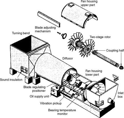
High efficiency and self-limiting characteristics are the advantages of the axial-flow fans, as can be seen in Figure 8.11. Axial fans for boilers are available in two types: single stage and two stage, depending on the number of stages of blades on the rotor (Figure 8.12). The flow and pressure are controlled by varying the blade angles. The axial fans are more expensive because of (1) blade movement mechanism, (2) superior manufacturing techniques, and
|
FIGURE 8.12 Two-stage variable-speed axial fan. (From TLT-Turbo GmbH. With permission.) |
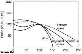
(3) higher quality of materials required. But they can maintain higher efficiencies at various boiler loads better than the centrifugal fans with their inlet vane controls (IVCs). With the increasing fuel costs, the use for axial fans is progressively increasing—at least for FD fan applications in utility boilers. However, the ID application presents the possibility of fan erosion, even with slightly higher or aggressive ash. Erosion of blades is the main concern, as they are made of Al or Mg alloys to reduce weight. This reduces the hub strength and bearing loads. The blades, in many cases, are protected by hardened steel strips, but the axial fans are still not considered suitable for ID for high ash or abrasive ash applications. The performance degradation on erosion is greater for axial fans than for centrifugal fans. As shown in Figure 8.13, the axial fans are
|
Volume (%) |
|
|
250 200 150 100 50 |
![]()
|
0 50 100 150 200 250 Volume (%) |
![]() FIGURE 8.13
FIGURE 8.13
Comparison of various fan characteristics.
Three basic laws govern the working of a fan: (1) speed, (2) density, and (3) diameter, which can be described as follows:
1. Based on speed
A. Volume is proportional to speed at constant density
|
(8.1) |
![]() QI _ NI
QI _ NI
Q2 _ N2
B. Static pressure is proportional to speed squared at constant density
|
P |
|
1 |
|
|
|
|
C. Horsepower is proportional to speed cubed at constant density
|
HP1 HP2 |
![]()
|
(8.3) |
V N2 y
|
|||||||||
|
|||||||||
3. Based on rotor diameter
A. For geometrically similar fans, volume and power are proportional to gas density at constant speed
|
‘ Di’[7] VD2/ |
|
|
|
|
|
(8.7) |
![]() ‘ Di’2
‘ Di’2
VD2y
B. For geometrically similar fans, revolutions per minute (rpm) are inversely proportional to the impeller diameter
|
|
||
|
|||
Geometric similarity of fans enables the prediction of performance. The main operating parameters of speed and diameter of the fans are linked by specific speed and specific diameter, respectively.
Specific speed is the rpm that delivers a unit volume at unit differential head of air under standard conditions.
Specific speed (NS) = (8.9)
Where N is the number of revolutions per minute and P the static pressure.
Specific diameter is the impeller diameter required to deliver a unit volume at unit differential head at unit specific speed.
DP14
Specific diameter (Ds) =
|
VQ |
![]() (8.10)
(8.10)
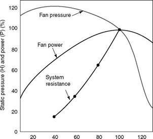
Fan selection begins with determining system resistance. System resistance is the total of all resistances that the fan is required to overcome. Typically, for an FD fan, the resistances are the airheaters (AHs), ducts, flow-measuring devices, firing equipment, etc. Correct estimation of system resistance at the maximum continuous rating (MCR) and other loads in head versus load (H-Q) format is the first step. Suitable margins are added to arrive at the design condition. The fan chosen should possess an H-Q characteristic that intersects the system resistance curve at the design point (Figure 8.14).
|
Design flow (Q) (%) FIGURE 8.14 System resistance versus fan curves. (From Power magazine. With permission.) |
It is necessary to have a substantially drooping characteristic for the fan to ensure only a single flow for a certain head in the fan-operating range. If a hump or flatness in the curve results more than one flow for a certain head, the fan tends to shift the operating point, causing hunting, that is, continuous load change and unstable operation. Also, the fan selected should give optimum efficiency at the MCR and normal continuous rating (NCR) conditions. The best efficiency condition should lie in the region where the fan operates for a maximum period and not necessarily at the design point.
Direct drive for fans is preferred, as it is the most compact arrangement with the least transmission losses. AC induction motors are the most common drives. Although a fan runs at one of the nominal synchronous speeds, the best efficiencies may not coincide with these speeds.
Centrifugal fans operate at nominal speeds of 3000, 1500, 1000, and 750 rpm, with most at 1500 and 1000 rpm. In the past, 600 rpm has also been used for very dusty applications. (Actual speeds are —3% lower due to slip in motor.)
The fan speed of 3000 rpm is only for clean air application requiring high heads, as in the case of SA, because of high noise level and excessive wear on bearings.
Likewise, 750 rpm is not preferred due to the large impeller diameter and heavy weight, producing high inertia, calling for star-delta starters to reduce the starting time. Also the dynamics are poor and lead to sluggish response. The entire arrangement is expensive due to the fan and motor assembly, special starters, heavy cables, and large foundation. Such low rpm is chosen only when excessive wear is expected from dusty gases. The fan selection is radial in most cases with the attendant poor fan efficiency calling for high-kilowatt motors. Wear liners on both impeller blades and casing, if chosen, worsen the dynamics. Induced draft fans required such construction in boilers with high-ash coal firing with only mechanical dust collectors (MDCs) upstream. With stricter pollution norms and the use of electrostatic precipitators (ESPs), 750 rpm speed is rare. For GR fans, with no dust separation possibility, 750 rpm may still be necessary in many cases, depending on the location of gas suction and the severity of erosion of ash.
Clean air application almost never demands a speed below 1000 rpm. In fact, 1500 rpm is better, as the fan and the motor are both smaller and the arrangement is cheaper. For ID and GR fans, 1000 rpm is the most common speed for solid fuel firing.
For small fans of up to —150 kW, belt drives are popular, as they enable the fans to run at the most efficiency despite slightly higher transmission losses. With the motor parallel to the fan, the arrangement can also suit a tight layout.
Margins on volume, head, and operating temperatures are added to the estimated MCR or peak system resistance points to arrive at the design conditions. The fan margins are essential for the following reasons:
• The pressure and draft losses calculated are the best approximations and need safety margins. The fuel analysis, air and gas weight calculations, and the assumptions in calculating the losses are accurate only within certain practical limits.
• There are bound to be differences in the geometry used for calculation and the boiler constructed due to inaccuracies in manufacturing and erection.
• The fouling of surfaces is unpredictable, particularly with fuels such as coal, and cannot be captured accurately.
• Any boiler that needs overfiring to catch up with rapid load ramps needs more power from the fans and the firing equipment. This requires spare power.
• Every fan has negative tolerances on head and volume due to manufacture. They must be compensated for if all the parameters are to be met in practice.
Excessive margins. Although it is imperative to provide correct margins, excessive provisioning is wasteful and injurious. Motors are provided with additional margins to
• Account for the positive power tolerance of the fan and the negative power tolerance of the motor and possible errors in the estimated figures of power
• Provide for a possible drop in system voltage and frequency
Considering that boilers normally operate at —80% of the MCR load most of the time, the loading of fan motors, even with normal margins, works out to —50 to 60% of the rated motor loading, which results in motor operation at a significantly lower efficiency. The initial costs of fan, motor, and electrical equipment are all higher too. With more generous margins, the situation worsens. Excessive auxiliary power consumption alone is a good enough reason to avoid unnecessarily large margins.
Margin range. Fan margin figures are continuously refined. There is a general consensus for the main fans, namely the FD and ID fans, that the margins for solid fuel-fired boiler should be around
• 20% for volume
• 44% for the variable head
• 20°C for the operating temperature
For liquid and gaseous fuels with little fouling tendency, the margins are lower at
• 10% for volume
• 21°% for the variable head
• 20°C for the operating temperature
These margins are for fans with medium-level manufacturing tolerances and usual negative tolerances for head and capacity. When fans of closely held manufacturing tolerances are chosen with no negative tolerance on head and capacity, the margins may be reduced by nearly half.
Typically, the margins indicated in the preceding text are for industrial boilers. For utilities, the margins are lower and the fan tolerances are also correspondingly lower.
The two types of fan efficiencies are (1) total/mechanical and (2) static.
1. Total/mechanical efficiency is the total energy in the stream, taking into account both static and velocity pressure, as a percentage of energy input to the fan.
2. Static efficiency takes into account only the static pressure output of the fan.
Static efficiency is used by manufacturers to specify the fan performance.
Fan power consumption can be expressed as
P • v. kVH
Power in hp _——————
Qc
Where
K = compressibility factor
V = inlet volume in cubic meters per hour or cubic feet per minute H = pressure rise across the fan in millimeter water gauge or inches c = constant 2743 (6354) n = fan static efficiency %
Compressibility factor is the ratio between the total pressure developed by a fan with an incompressible fluid and the total pressure developed with a compressible fluid, all other conditions remaining the same.
Compressibility factor 1.0 1.05 1.1 1.15
Pressure ratio 1.0 0.98 0.97 0.95
Fan power in kilowatts, in SI units, is also given by the same formula
Power (kW) _ kVH (8.11)
Qc
Where V is in cubic meters per second and H in kilopascals; c = 1, and n is percent efficiency.
It can also be expressed as
1T47 0.1 X k X V X H
KW =———————————— (8.12)
Qc
Where H is in millibars.
The two methods of centrifugal fan control are:
1. Variation of outlet or inlet duct dampers at constant speed
2. Variation of fan speed
Axial fans are controlled only by a variation of blade angle.
This is the least efficient of all the methods, as it is the throttling of the outlet pressure across the damper after the fluid has been pressurized by the fan. A lot of power is wasted. The outlet damper adds resistance to the system and moves the operating point up the fan curve, thereby reducing the output. Its main advantages are
• Extreme simplicity of construction and operation
• Adaptability to stepless autocontrol
• Cost reduction via shorter shaft length.
Outlet damper control (Figure 8.15) alone is employed only on relatively small fans where the control required is nominal. It may be combined with IVC for enhancing the range and fineness of control.
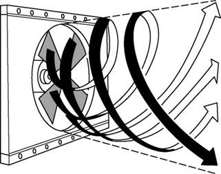
 This is the most popular mode of fan control. The inlet air or gas is given a spin in the direction of the wheel rotation, thereby imparting nearly the same effect as reduction
|
|
FIGURE 8.15
Action of fan outlet damper.
|
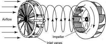
FIGURE 8.16 Action of inlet vane control. (From Power magazine. With permission.) |
Of the speed. Depending on the degree of spin, the outlet pressure and discharge are reduced. IVC has a set of aerodynamically shaped vanes for providing the correct spin (Figure 8.16).
IVC advantages are as follows:
• Efficiency and low cost.
• The variation is stepless and amenable to autocontrol.
• Ruggedness and reliability with low hysteresis.
• Reduced space requirement.
The main limitations are as follows:
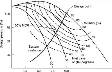
• The IVC is highly prone to erosion with ash-laden gases. In a dusty environment such as the inlet of ID fan, the IVC located at the inlet eye of the fan, is replaced by differential damper control (DDC) located at the inlet of the inlet air box. Differential damper control consists of specially shaped dampers to provide optimum spin with reduced inlet losses approaching the IVC.
• It is not cost-effective for a wide range of load control, as the power consumption at lower loads is higher as compared with speed variation.
Figure 8.17 gives typical characteristic curves of a fan equipped with IVC.
This is the most efficient control and also the most expensive and justified only if the savings in power cost can really offset the high initial expense. This has gained a lot of acceptance in recent years due to minimization of auxiliary power. Several types of speed variation methods include.
1.Variable-speed hydraulic couplings (HCs) or fluid drives
2.Variable frequency AC motors
3.Slip ring motors
4.DC motors
5.Drive turbines
6.Two-speed motors with IVC
|
Design flow (%) FIGURE 8.17 Typical curves for inlet vane control. |
Hydraulic Couplings (HCs)
HCs of fixed speed type are regularly employed where high-starting loads are connected to motors for transferring the load with a time delay. This allows adequate time for the motor to attain enough speed and torque to take on the heavy load smoothly. Motors in coal handling plants and coal pulverizers are some examples in a power plant. The input and output shafts have no physical contacts. Hydraulic oil is put into motion by an impeller on the input shaft, which transmits the torque to an identical impeller on the output shaft, called the runner. The output shaft attains nearly the same speed as the input shaft after a short time. The speed difference between the two shafts is the slip that enables the motor to start smoothly and reach a speed at which it is connected to the heavy load.
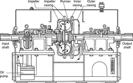
Variable-speed hydraulic couplings (VSHCs) or fluid drives have a provision of scooping off oil from the sump so that the torque is lowered and the speed of the output shaft is limited. The motor, however, maintains its constant speed. The speed control is thus effected by the scoop control, which transfers oil in and out of the chamber, depending on the signal.
Figures 8.18 and 8.19 depict fluid drive and the working principle. The impeller, which provides acceleration to the oil, is keyed to the drive shaft and housed inside the impeller casing. The runner is keyed to the output shaft and is housed in the inner casing. A constant-speed pump maintains oil in the chamber created by impeller and inner casings. In the outer casing, the scoop tube helps to transfer the oil out of the circulation, thereby changing the slip between the impeller and the runner disks.
Fluid drives are among the most efficient, particularly at low speeds because the power consumption of the fan varies as the cube of the speed, while the loss in HC is proportional only to the slip. The difference is the power saving, which increases as the speed is lowered.
Fluid drive couplings are:
• Very rugged and reliable
• Available even in very large sizes
• Amenable to stepless automatic control
|
FIGURE 8.18 Power transmission in hydraulic coupling. |
|
|
FIGURE 8.19
Load variation by scoop control.
Variable Frequency AC Motors
These motors employ a frequency control panel by which the output frequency (f ) is varied, which, in turn, regulates the speed of the motor as given by the formula
N = 120 X — p
Where p is the number of poles in the motor.
The variable frequency drives (VFDs) have become very popular as their range has increased and their cost decreased. With practically no maintenance, the VFDs are good choices.
Slip Ring or Wound-Rotor Induction Motors
These motors are popular among certain industries. They are usually suitable for sizes up to —250 kW. Here the rotor slip energy, conventionally wasted in resistor banks, is inverted and fed back into the power line. The electronics are relatively simple and inexpensive.
DC Motors
These motors are sometimes used for industrial fan drives for their reliability despite their higher initial and maintenance costs.
Drive Turbines
Despite their higher initial and maintenance costs, drive turbines make a good choice in process industries. They are very popular in industries such as refineries, petrochemicals, and sugar, where there are several pressure levels of steam, and the exhaust steam from drive turbines can be used in the process. They tend to improve the overall efficiency of the plant because they consume steam directly and not the power generated from steam.
• Drive turbines have practically no size limitation.
• The range of speed variation is also high.
• Normally for sizes above 50 kW, drive turbines can be considered.
Two-Speed Motors with Inlet Vane Control
This solution applies to very large motors. Two-speed two-winding motors are bulky and costly but offer a lower-cost solution if VFDs and VSHCs work out to be more expensive.
Figure 8.20 compares the various methods of fan control based on power consumption at different part loads. Speed variation for centrifugal fans and variable pitch control
For axial fans are the most efficient methods, approaching theoretical power consumption limits. Hydraulic drives are less efficient. Two-speed fans with IVC can provide low power.
In selecting a speed control mechanism, the important thing to assess is the variation in fan output required in actual operation. More efficient and expensive methods are justified only when operation at lower loads is called for.
Centrifugal fans can be classified in several ways besides the shapes of blading, which are described in the following section.
Centrifugal fans can be
1. Overhung
2. Simply supported
1. Overhung design. The impeller is mounted on one end of the shaft, which is supported usually on a pair of bearings on the motor side (Figure 8.21).
A. With no bearing on the nondriving end, the fan shaft is shorter.
B. The fan and foundation are compact, simple, and cheap.
C. This is the most compact and economical design.
It is generally good for clean air application and lower capacities. Smaller FD and SA fans are usually overhung.
Impeller on motor shaft. For very small fans, such as SA fans of small boilers, seal air fans for mills, or scanner air fans, the impellers can be mounted on the motor shaft producing a compact and economical arrangement, as the bearings
|
FIGURE 8.21 Overhung fan with single inlet and single width of impeller. |
Between fan and motor are avoided. The only limitation other than size is that it has to be strictly used for a cold air application.
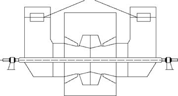
2. Simply supported design. The impeller is supported on both sides of the fan making the arrangement (Figures 8.22 and 8.23)
A. More robust, heavy, and large
B. Suitable for dusty and large applications
|
FIGURE 8.23 Double-inlet double-width fan. |
![]() In both applications, usually the shaft is designed for a first critical speed much higher than the operating speed, normally 1.4 times, and hence stiff shaft design. This makes the impeller strong and avoids fan vibrations. In large fans, it is sometimes economical to have only a flexible shaft design, where the first critical speed is within the operating speed as a minimum. In such cases, fan control by speed variation is best avoided, or done carefully by avoiding near-critical speed.
In both applications, usually the shaft is designed for a first critical speed much higher than the operating speed, normally 1.4 times, and hence stiff shaft design. This makes the impeller strong and avoids fan vibrations. In large fans, it is sometimes economical to have only a flexible shaft design, where the first critical speed is within the operating speed as a minimum. In such cases, fan control by speed variation is best avoided, or done carefully by avoiding near-critical speed.
|
FIGURE 8.22 Simply supported fans with single inlet and single width of impeller. |
|
Differential damper control
|
Centrifugal fans can have:
1. Single inlets
2. Double inlets
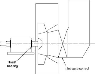
1. Single-inlet fans with single width of impellers are more economical for capacities up to 50 m3/s (—100,000 ft3 m). They need a thrust bearing on the opposite side of gas entry to counter the axial force created (Figures 8.21 and 8.23).
2. Double-inlet fans with double-width impellers are more economical for larger capacities, although they have (Figure 8.23)
A. Wider impellers
B. Heavier and longer shafts
C. Two air boxes with two inlet dampers and controls
D. Heavier bearings due to longer bearing distances The double-inlet fans have the following advantages:
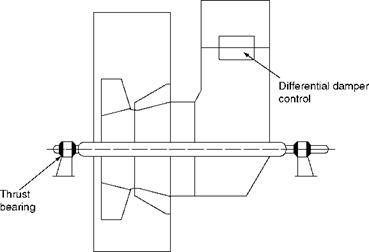
• They do not need thrust bearings, as the gas enters on both sides.
• They are more stable against vibrations and better suited for dusty applications than single width fans.
The overhung fan has a pair of bearings on the motor side and IVC on the other side. The simply supported fans have inlet damper controls. The increase in the shaft length and impeller heaviness must be considered in the double-inlet design.
The possible types are direct, belt, and dual drives.
• Direct drive is the most popular because it is simple and calls for little maintenance. But the fan may have to operate at its off-peak efficiency, as the rpm may not coincide with the optimum speed. However, for high-capacity applications, direct drive is the only solution.
• Belt drive can be opted up to —150 kW and can save space. The best operating speed as per H-Q curves can be chosen by suitable pulley selection. But the issues associated with this drive are belt slackening and replacement due to wear.
• Dual drive is occasionally employed in the process industries such as refineries, where a fan is driven by motor and turbine on either side, to enable boiler black start (on power from grid or diesel set) or enhance the availability.
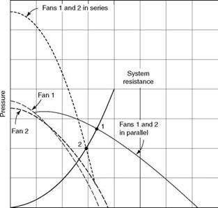
Fans can be operated in series or parallel mode depending on the system requirement. The fans are placed
• In series operation when the pressure needs to be built up (Figure 8.24)
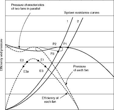
• In parallel operation when volume needs to be built up (Figure 8.25)
|
Capacity FIGURE 8.24 Fan operation in series and parallel. (From Power magazine. With permission.) |
|
Capacity FIGURE 8.25 Comparison of fans in parallel operation. (From Power magazine. With permission.) |
A primary air (PA) fan drawing suction from the AH, which is downstream of the FD fan in pulverized fuel (PF) boiler, is an example of series operation. FD and ID fan operations are other examples. A pair of FD fans or ID fans or a number of PA fans operating simultaneously are examples of parallel operation.
Dissimilar fans can be in series operation, even an axial fan and a centrifugal fan, but for parallel operation, the fans have to be very similar with continuously drooping characteristics with no humps to prevent unstable operation, leading to dangerous hunting. Hunting occurs when there is a hump in the fan and it keeps shifting its operation from high to low volumes.
Single Set and Two Sets of Fans
It is normal to have a single set of fans for smaller boilers and two sets of fans for the larger ones. Single set of fans has the advantage of
• Simplicity of arrangement
• Reduced duct work
• Less instrumentation and control
• Better efficiency
• Lower auxiliary power due to larger size
Single sets permit lower installation and running costs. Two sets of fans, however, provide redundancy while sacrificing the above-mentioned benefits. Induced draft fan erosion was the main reason behind the adoption of two sets of fans, even for midsize boilers. With very reliable ESPs, fabric filters (FFs), and superior fans, the single-fan concept is gaining greater acceptance.
Fan erosion is experienced mainly in coal-fired boilers. Coal ash impinging at high velocities is the main reason for this erosion. Induced draft and GR are the usual fans in a power plant, which are susceptible to erosion. With the adoption of ESPs and bag filters, ID fans have largely overcome this problem. GR fans, however, continue to experience high dust loads and hence are made of radial blading to resist erosion. The PA fans in suction mills are also prone to erosion. Depending on the gas flow and fan construction, the areas of wear can be predicted and identified.
• Overlaying weld material on selected areas of impeller
• Providing replaceable liners
These are the two methods of protecting the centrifugal fans against erosion of ash besides lower speeds, but they increase the impeller weight. Increase in fan weight leads to poorer boiler dynamics and longer start-up times. On the whole, there is no fully satisfactory solution for the problem of fan wear.
1. Deposition of weld material of a hard composition, such as chromium carbide, on the blades and the inside channel, which come in contact with moving gas, is a very common remedy. A careful judgment is needed regarding the exact location and amount of deposition, as the inertia of the impeller increases with any weight addition. Flame or plasma spray metallizing is not very popular because it can peel off if not applied properly. More importantly, the alloying left behind interferes with any later weldments. Metallizing is capable of withstanding nearly perpendicular impingement but not tangential abrasive forces.
2. Replaceable liners can be provided for blades or casing or both, depending on the protection needed. They are soft sacrificial plates, either bolted or welded. Bolted blades also need bead welding to prevent entry of dust particles under the plate. Ceramic or tungsten carbide tiles are attractive due to their extreme hardness, low thickness, and light weight. But the problem of securing the fan blades is not fully solved.
For variable pitch axial fans, protection is needed on the upstream edges of the blades, which is provided by stainless steel (ss) or chrome strips attached by ss screws. Complete blade sets must be replaced after detecting erosion, and this can be usually done in a single shift by the maintenance staff. The erosion protection for axial fans is thus easier, but the capability to withstand erosion is inherently lower in axial fans.
A boiler plant, depending on the firing system and size, contains several fans of various sizes and types:
• Forced draft fan is the main air fan whose prime job is to deliver the combustion air to the firing equipment in a balanced draft boiler. In a pressurized boiler, the FD fan has to further push the gases formed in the combustion chamber up to the chimney exit.
• A forced draft fan takes clean cold air from the atmosphere, unless steam AHs are in the circuit, in which case the inlet air is slightly hotter.
• In cold countries, it is normal for warm air to be drawn from the top of the boiler house. The tall suction duct can also be used for airflow measurement.
• Forced draft fan heads vary from as low as —50 mm wg in stoker-fired boilers to as high as —2000 mm wg and higher in circulating fluidized bed combustion (CFBC) boilers.
• In the case of PF boilers, FD fans supply only SA as the PA fans supply the PA.
• Backward-curved or aerofoil type of centrifugal fans mostly with IVCs, are usually adopted here. In utility boilers, FD is the most ideal application for axial fans with variable pitch.
• Induced draft fans, employed only in balanced draft boilers, suck the combustion gases from the furnace and discharge them at the stack exit. They maintain a nominal suction of 5-25 mm wg in the furnace to avoid flames leaping out, and ensure operator safety and prevent the insulation and casing from burning out.
• Induced draft fans are hot gas fans with temperatures usually —150°C and rarely exceeding 200°C.
• Suction pressures vary from —200 to 400 mm wg. Higher pressures are required when dust separation devices such as bag filters or wet scrubbers (WS) are employed.
• When dust collection from flue gases was not mandatory, radial or backward — curved radial-tipped blading was used in centrifugal fans. With reliable gas
Cleaning equipment in use, fans with aerofoil, backward-curved or backward — curved radial-tipped blading are used, depending on the efficiency of the dust collectors and the erosive nature of the fly ash. Aerofoil blading is also common now.
• Variable pitch axial fans are also used where the fly ash is not erosive and the upstream dust collection is good.
• Corrosion of fans is an issue only for liquor or refuse-fired boilers.
• Secondary air fans or over-fire air (OFA) fans are used for providing 10-30% combustion air to the furnace at high pressure to (1) provide turbulence and (2) prevent stratification of gas streams so that the combustion is complete. More volatile matter (VM) in fuel increases the OFA requirement, as more combustion takes place in the furnace. In the case of staged combustion for NOx abatement, these fans provide much higher amounts of air, even as high as 50%.
• Pressures vary from 250 to 1000 mm wg.
• Aerofoil or backward-bladed construction is suitable.
• Both cold and hot air are used. Hot air can be as high as 350°C, demanding special care for bearing cooling.
• Gas tempering (GT) and GR fans are high-temperature fans and, in case of solid fuel firing, they are also high-dust fans. The gas temperature is dependent on the location of suction—whether the economizer (ECON) or the AH exit.
• Only centrifugal fans with radial or radial-tipped blading are suitable for this application, depending on the dust loading and its erosivity.
• These fans have the most severe duty in the power plant, as they are subjected to high-dust loads and high temperatures with wide fluctuations.
• Care should be taken to select a fan with integral hub and shaft, as shrink fitting may not be adequate.
• Primary air fans in PF boilers draw hot air from the discharge of AH and push the hot PA through the mills and carry the pulverized coal to the burners. A cold PA fan takes ambient air and passes it through the AH additionally. Air quantities are relatively small, and the heads are high, requiring a narrow wheel with large diameter. As the hot air is usually dusty with rotary AHs, the hot PA fans use radial blading. The cold PA fans, on the other hand, deal with clean air and can be made with aerofoil blading.
• Exhauster fans downstream of the coal mills in suction-type PF firing are always made of straight radial blading to withstand erosion of coal dust.


 29 августа, 2013
  admin
admin 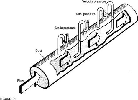


 Опубликовано в рубрике