Spreader Firing: CG and RG with Spreader Stokers
This is the most common method due to its very high fuel flexibility, excellent multifuel capability, very good load dynamics and operational simplicity, reliability, and safety.
Combustion Process in Spreader Firing
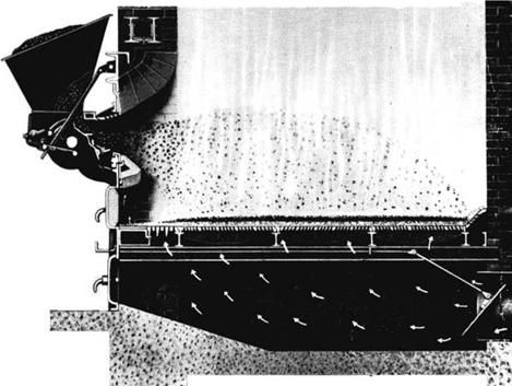
This process is characterized by a two-stage burning—suspension mode in furnace and bed mode on grate. The combustion sequence can be described as follows:
• Moistened coal is metered and distributed on to the grate by means of spreaders.
• Larger coal pieces fall toward the rear and smaller ones to the front. Hence, the direction of grate travel is toward the feeders to permit longer residence for the larger coal particles.
• Volatiles and fines burn in flight in suspension releasing —35 to 50% of fuel heat. For high-volatile fuels this proportion is 40-60% of heat.
• The bed formed on grate consists of dried and devolatilized particles in ignited condition. The bed is thinner at 50-80 mm and hence the combustion is faster. The higher burning speed is also due to burning both from top and bottom due to radiation from the furnace and airflow from the grate.
• Air, 20-30%, is provided above grate as overfire air (OFA) or SA to support the suspension firing.
• As the furnace radiation provides the necessary heat for ignition and sustenance of combustion, the long furnace arches to deflect hot air are not needed. However, strategically positioned high-pressure SA jets are necessary to agitate the flames and provide turbulence to prevent stratification of gas flows.
• For high-volatile fuels, tertiary air (TA) is also provided below the furnace nose to burn the escaping VM and prevent fines from entering convection passes by providing an air curtain.
• The important differences between the combustion processes of MB and spreader firing are as follows:
— There is significant combustion in suspension with spreader firing in flight.
— The devolatilized layer of fuel burns at both the top and the bottom surfaces on the grate at high speeds.
— The two-in-one combustion of spreader firing naturally releases much higher
Heat for the same grate area and furnace volume—nearly double—making it a
Very compact, fuel efficient, and dynamically responsive system.
Design Aspects of Spreader Firing
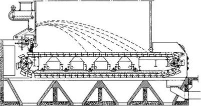
Figure 11.9 depicts a typical SS.
• As the fuel burns partly in suspension, liberating 35-50% (40-60% for high-volatile fuels) of fuel heat and rest on the grate in a thin film of 50-80 mm thickness, the combustion and response to load swings are very fast.
• In TGs/CGs ash discharge is continuous, unlike the intermittent de-ashing in the DG, making the plant output steady and its efficiency better.
• A seamless load turndown of 3:1 is possible.
• Fuel throw, rather than the mechanical force of de-ashing, is the deciding factor in determining the grate length. Hence stoker net lengths of approximately
• 5.5 m (18 ft) for coal
• 6.4 m (21 ft) for biofuels
Are possible (add —500 mm for shaft center distance) against a maximum of —5 m (net) for DGs. These dimensions can vary among manufacturers.
• Grate widths of up to 6.1 m (20 ft) are built with single drive, limited by torsional strength of the drive shaft. Thus, grates as large as —66 and 77 m2 (710 and 830 ft2) of net area can be built for coal and biofuel firing, respectively.
• Possible heat release rates (HRRs) are as high as
• 2.37 MW/m2 or 2.03 X 10⁶ kcal/m2/h or 750,000 Btu/ft2/h on coal
• 3.47 MW/m2 or 2.98 X 10⁶ kcal/m2/h or 1,100,000 Btu/ft2/h on bagasse and woodchips
|
Fuel Hopper
FIGURE 11.9 Spreader stoker with traveling grate. |
• The important limitations are as follows:
— Heat input per meter width of furnace should be < —14.2 MJ/h or 3.4 X 10⁶ kcal/h or 13.5 MBtu/h to avoid slagging.
— Ash discharge should be <530 kg/m/h (350 lb/ft/h) to limit unburnt loss.
• Grate bars are protected from the intense furnace heat by the thin layer of ash produced after the burning of fuel. Hence for coal firing a minimum of 7% ash is required. For biofuels with 2-4% ash the grate speed is lowered and the ash layer is allowed to build up. Alloy grate bars may be needed to improve the ability of grate to withstand the radiation.
• Excess air at full load can be limited to 30% with modern stokers, gradually rising up to 50% at half load.
• Primary air pressure below the stoker is required at —40 mm (1.5 in.) w. g. Air velocities through the bed are —1 m/s. Area for air is 6-10% of the grate area.
• Secondary air or OFA through two sets of air nozzles at the rear and one set in the front wall is provided to
— Penetrate the burning zone and agitate the flames.
— Create turbulence for better combustion.
— Prevent stratification of gas flow.
— Approximately 20% of total airflow is secondary, provided at —600 to 750 mm wg.
• In bagasse and biogas applications in which air-swept spouts are employed for fuel spreading, another 10% air is added to the capacity of the SA fan. An additional set of nozzles is also added to reduce carryover if the fuel is suspected to have more fine fibers.
• Using hot or cold air for SA has been a debated but an unresolved issue.
• Cold air is denser and hence can penetrate the furnace better and agitate the combustion products but it cools the flames.
• Hot air has the opposite effect. The high-speed hot-air fans require more power and maintenance.
• Because of large suspension firing and high flue-gas velocities, ash carryover is nearly 20-40%, depending on the fines in fuel. Combustibles in fly ash are —20%. In the 60-70% coarse ash discharged from the grate, the combustibles are —10%. Unburnt carbon loss goes up sharply from —3-4% for good coals of —20% ash to 10-12% for high-ash coals of 40-45% ash, with correspondingly higher erosion of PPs.
• The dust carried over in SS is grittier and hence higher in carbon. This devolatilized char is difficult to burn as it needs ignition temperatures >700°C. Therefore, it makes sense to return ash from only boiler bank (BB) and similar high-temperature hoppers and subject the devolatilized fine particles to intense heat again to reduce the unburnt carbon loss. Higher recirculation means more carbon recovery and chances of the erosion of the PP, refractory, and grit recirculation system. For high — ash coals it is normal to restrict recirculation only from the BB hoppers. Typically there can be —2% reduction in carbon loss.
• For low-rank fuels such as lignite and biofuels, the grit refiring is not useful as fuel burning is good and the carbon burn-up efficiency is inherently in excess of 95%. No significant unburnt carbon will be present in the ash particles.
• Arranging the required number of feeders for furnace width is a challenge at higher capacities. When both coal and biofuels have to be burnt, the answer requires twice as many feeders. Furnace width is then governed more by the feeder consideration than by the permissible HRR. A compact fuel feeder is required, particularly at higher capacities.
Spreader Firing versus Fluidized Bed Combustion Boilers
The comparison is fuel dependent.
Coal
Fluidized bed combustion boilers score over spreaders in coal firing due to better
• Combustion efficiency (between 5 and 10% depending on ash in coal)
• Tolerance to fines in coal (30% through 1 mm against 30% through 3 mm or —15% through 1 mm)
• Environmental compliance (lower NOX and possibility of in-furnace desulfurization)
• Maintenance and reliability; absence of moving hot parts
• Ability to burn inferior coals with much higher burden (A + M) of —65% and gross calorific value (GCV) as low as 2000 kcal/kg
Despite the disadvantages of
• Additional coal crushing
• Bed tube and coal pipe erosion
• Lower and step-type turndown
• Inelegant ash disposal
• Higher forced draft (FD) air pressure
The fuel savings of FBC boilers far outweigh their drawbacks.
Biofuels
The principal advantages of FBC are
• High carbon burn-up efficiency
• Low-temperature combustion
• In situ desulfurization
Which result in good fuel efficiency and ecological compliance. In biofuels, where fuel ash is low, stokers are better for most applications.
• Biofuels, with inherently high moisture and low N2, produce low flame temperature (due to the quenching effect of fuel moisture) to generate no offending quantities of fuel and thermal NOx.
• Negligible S in biofuels produces no SOx, dispensing with the need for desulfurization.
• Cellulosic fuels with low ash and high VM allow rapid combustion with carbon burn-up efficiencies of —96-98%.
FBC presents no particular advantages. It does not easily burn biofuels that have high VM and moisture contents because:
• They are not easy to size
• They are light and fluffy and do not stay in bed.
• It is difficult to maintain the bed temperature as the fuel tends to burn more in suspension.
• There is a continuous need for bed ash replenishment.
Selected biofuels, such as rice husks which are properly sized and have high FC are also amenable for burning in FBC.
Bagasse and wood chips are well suited for spreaders and large-capacity boilers. Stoker — fired bagasse boilers as large as 250 tph are available. In bagasse-based cogen, bagasse is not always available and multifuel boilers are required to burn coal or oil as alternate fuel.
Feeders and spreaders have the following two functions:
1. The feeder for calibration and regulation
2. The spreader for evenly distributing fuel onto the grate section
For a compact fuel such as coal, it is possible to combine both tasks into a single unit that can be bolted to the furnace casing. The processes are almost always separate for the fluffy and voluminous biofuels. Also the rotary mechanical spreader is ill-suited for biofuels where pneumatic distribution is appropriate. The spreader is bolted to the furnace whereas the feeder is located below the fuel hopper.
|
|
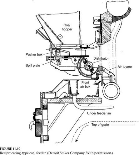
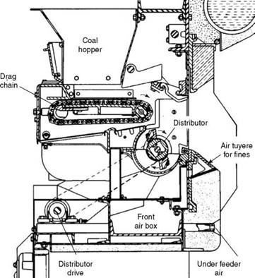
The feeders in the integrated systems are of three types (Figures 11.10 through 11.12):
1. Reciprocating
2. Rotary
3. Chain
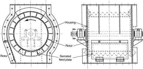
Mechanical spreaders are always variable speed rotary drums (Table 11.3). The spreader drums or rotors are equipped with sinusoidal or inclined plates for good lateral distribution. A set of three to five plates is —150 mm long, and is made of heat-resistant alloy, bolted to the spreader drum.
Normally, there are two or four sets of plates around the rotor. In the total feeder assembly, the spreader drum encounters furnace radiation, and to keep it safe from overheating and subsequent warpage, the shaft bearings on either side are water-cooled. Also, in a running boiler, rotors of idle feeders are always kept rotating to prevent overheating. Adjustments to the trajectory are required to suit various grate lengths and also fuel properties and sizing. This is achieved by varying the spreader speed. Spreaders are mostly of the overthrow type. Air nozzles located below the spreaders help to prevent cascading of fines
|
Air tuyeres for fines |
![]()
|
Coal gate E=Ј |
![]() FIGURE 11.11
FIGURE 11.11
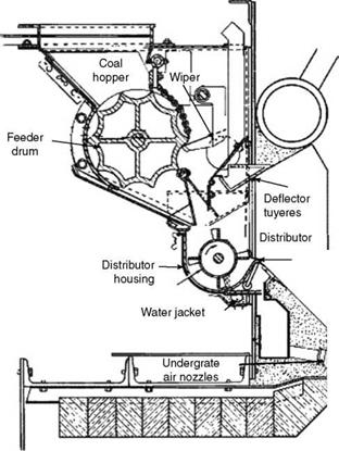
Rotary-type coal feeder.
Onto the grate by blowing them into the active combustion zone. Underthrow spreaders provide a more horizontal trajectory for dealing with fuels with higher fines and moisture. They are more popular with FBC boilers.
All feeders are volumetric devices and hence the fuel size and characteristics are important. Higher moisture leads to lump formation, upsetting the calibration. Coal fines cause erosion. An isolating plate for each feeder at the bottom of the hopper is essential to permit the removal of the feeder for maintenance in a running boiler.
1. Reciprocating feeders shown in Figure 11.10 are simple, compact, and lightweight. The reciprocating pusher box at the bottom of the coal hopper pushes the coal resting on the spill plate onto the spreader. Coal quantity is varied by adjusting the stroke length of the pusher box in response to the load. The limitations of this design are as follows:
A. Higher fines and moisture disrupt the feeder calibration.
B. Fines settle between pusher box and pusher plate, leading to faster erosion, further aggravating the problem. A good limit for moisture is 10%.
2. Rotary feeders shown in Figure 11.11 are more robust, and deal better with higher moisture and fines without undue erosion. A cut-off gate maintains the depth of coal. Drum speed is variable, and it automatically controls the output in response to load.
|
FIGURE 11.12 Chain-type coal feeder. (Detroit Stoker Company. With permission.) |
|
TABLE 11.3 Approximate Spreader Sizes and Capacities (kg/h) for Coal
|
There is a wiper arrangement to keep the feeder drum free of coal dust, even with high moisture, so that the calibration is not affected by fines and moisture.
3. Chain feeders shown in Figure 11.12 are the heaviest, have almost twice the capacity, and are more expensive. Speed variation of the feeder regulates the output. This design can deal with higher fines and moisture up to 20%, and erosion issues are minimal.
Boiler load control. Feeders are usually controlled by individual speed controls. Anticipatory signal from steam pressure first varies the FD fan speed and instantly raises or reduces the air quantity and in turn heat from the grate. This is followed by the signal from the steam flow, which varies the (1) fuel flow by concurrently varying the speeds of all feeders and (2) grate speed where necessary. Airflow is slowly restored to the new level. This anticipatory action results in an extremely fast load response due to an active fuel inventory on the grate. The spreader’s revolutions per minute are manually set for specific fuel and size.
|
|
FIGURE 11.13
Mechanical rotary distributor or spreader for coals.
Integral or separate fuel feeder plus spreader. For high-ash coals with large throughputs or where firing of coal along with another solid fuel such as bagasse or biomass is required, it is difficult to accommodate all the feeders on the front wall. The feeder and distributor are then separated and a long screw or chain feeder is provided from bunker to spreader.
Overthrow or underthrow spreaders or distributors. Spreading coal on the grate in an overthrow manner has been the common practice. The advantage is a minimal contact of coal particles with the rotor blades and the housing, thereby reducing wear. It is also helpful to have a longer trajectory as the fuel particles need only a peripheral push. The essential difference in spreading the fuel in FBC and SS is that the fuel is spread uniformly in FBC, whereas it is spread in the rear half in SS. In FBC, where there is no travel of the grate, a wider and more uniform distribution is needed. This could be achieved by underthrowing the coal. The coal stays in contact with the blades and the housing for a longer time. The trajectory is more horizontal and distribution of fines is more consistent. For high ash and high fines in coal, the underthrow feeders are better selections even for SS.
Independent feeders and spreaders. Layout considerations, particularly when multiple fuels are required, may have to be discarded in favor of separate units. For coal the feeders are usually chain or screw, and the distributors are rotary mechanical, as shown in Figure 11.13.
Bagasse or Biomass Feeders and Spreaders
In coal firing, it is normal to have the feeder and spreader in one assembly in a compact arrangement of the plant with bunkers close to the boiler. Coal, with its high CV and lower flow, makes it possible to have such a combined mechanism. With biofuels, the feeder and spreader should be separated as the fuels have low CV and are voluminous. These feeders are normally of three types:
1. Rotary
2. Screw
1. Pneumatic
2. Rotary
The connecting chutes between the feeders and the distributors or spreaders should be
• Steep, preferably at 60° or more, to the horizontal.
• Tapering outward, with increasing cross section, so that the fuel does not pack up and disrupt the flow. The feeders and spreaders are available in 600 and 750 mm nominal widths.
Variable speed arrangements drive the feeders. The feeder speed variation is the means to control the boiler load. As the fuels are voluminous and fluffy, the feeders are to be generously sized to prevent jamming. It is normal to place the motor and variable speed assembly in parallel behind the feeder to achieve access all around and to accommodate all the required feeders. Typical capacities of rotary feeders on bagasse are 8 and 11 tph approximately for 600 and 750 mm, respectively (Figure 11.14).
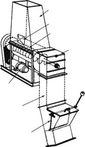
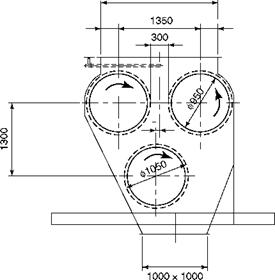
Figure 11.15 shows a typical screw-type feeder that commonly used with many biofuels that are not too fluffy. For large-capacity bagasse-fired boilers, the volume of fuel is larger, and with the number of standard feeders the grate width increases, making the boilers expensive. Large-capacity feeders with a nominal 1000 mm width with three rollers are now used as depicted in Figure 11.16. The advantage of the three-roll design is that it is possible to have fuel in a large vertical chute of even 10 m height. Bagasse store cannot be stored in a bunker. It needs a continuously expanding chute to make it flow smoothly. To extract bagasse and make it flow well, the top rollers move in an inward fashion, clockwise and anticlockwise, and discharge onto the bottom roller, which, in turn, moves clockwise to effect a positive discharge. The rollers are provided with toothed plates on the periphery as in conventional rotary feeders to prevent jamming of bagasse.
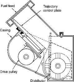
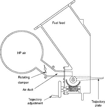
Spreading of metered biofuel is done by pneumatic distributors (Figure 11.17). Mechanical distributors are unsatisfactory as the fuels are light and fluffy. The pneumatic distributors, bolted on the furnace wall, are provided with trajectory adjustment for correcting the flight path and pulsating airflow for fuel throw.
|
FIGURE 11.14 Rotary feeder for bagasse and rice husk. |
|
FIGURE 11.17 Pneumatic distributor or spreader for biofuels. |
|
Fuel hopper (expanding sides) Access door |
![]()
|
Expanding Screw |
![]()
|
Discharge chute |
![]()
|
Shutoff damper |
![]()
|
FIGURE 11.15 Screw feeder for biofuels. |
![]()
|
Inspection Door |
![]()
|
2000×1000 |
![]()
|
FIGURE 11.16 Three-drum bagasse feeders. |
![]()
|
Typical dimensions |
![]()
|
Drive motor variable speed |
![]()
|
FIGURE 11.18 Catenary-type traveling grate. |
|
FIGURE 11.19 Chain-type traveling grate. |
Two important features of these grates are that they are (1) endless chains and (2) air-
Cooled with the aid of undergrate PA.
Grate types. By the way of stoker arrangement, these grates can be classified into two types:
1. Catenary (Figure 11.18)
2. Chain (Figure 11.19)
Catenary-type grates employ two types of grate bars or links:
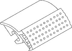
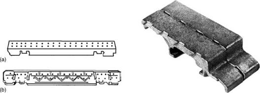
1. Plate (—300 mm) as in Figure 11.20
2. Bar (1000-1200 mm) as in Figure 11.21
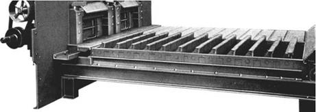
Chain-type grates usually employ grate bars of link (—25 mm) type (Figure 11.22).
1. Catenary-type grate. The return strand is not taut but is allowed a slack, consistent with the access and other requirements, at times with suitable adjustable guide rails below to maintain an effective shape. The grate remains under tension as shown in Figure 11.18. There is no need for additional chain tensioning. Solid shafts are employed. The grate moves from rear to front, and the front shaft is usually the drive shaft. A pair of chains spaced at —1.2 m forms a grate section and carries T-bars or bulb bars which in turn, carry the grate bars. The grate bars experience no tensile forces whereas the T-bars are subject to flexure, and the chains
|
|
|
FIGURE 11.21 FIGURE 11.22 Bar-type casting. (a) Top view. (b) Bottom view. Link-type casting. |
|
FIGURE 11.20 Plate-type (~300 mm) casting. |
![]() Are under tension. Plate-type grate bars can be considered as several grate links joined together and air nozzles drilled in the body and supported in the same way on T-bars. In the design that employs long grate bars of 1-1.2 m, the bars are directly connected to the chains. These bars are required to be heavy to withstand the flexure. Air is provided at the bottom and there is no segmentation of the windbox. The high-pressure drop in the Venturi-type air nozzles ensures uniform air distribution without internal dampering.
Are under tension. Plate-type grate bars can be considered as several grate links joined together and air nozzles drilled in the body and supported in the same way on T-bars. In the design that employs long grate bars of 1-1.2 m, the bars are directly connected to the chains. These bars are required to be heavy to withstand the flexure. Air is provided at the bottom and there is no segmentation of the windbox. The high-pressure drop in the Venturi-type air nozzles ensures uniform air distribution without internal dampering.
2. Chain-type grate. The return strand is supported by bottom rails (Figure 11.19). A separate chain tensioning arrangement is provided to keep the entire grate surface taut and flat. The upper and lower strands are —1000 mm apart to allow access and provide air dampers and seals. The shafts must be large and are made of hollow pipes to reduce weight. Air can be admitted from the bottom hopper or from the sides. Individual control of air to the various zones along the grate length is possible and represents an advantage over the other design. Sealing arrangements between the zones have to be carefully done and entail a lot of castings.
A. Grate bars. It is essential that the head and tail of the grate bars are perfectly matched to the preceding and succeeding grate bar, and all of them mesh with each other perfectly so that there is no air leakage between them. This is particularly important as the grate bars turn around at the ends.
Grate bars are provided with deep ribs, which make them mechanically strong and keep them close to the incoming air temperature by good cooling. The temperature of grate bars in a running boiler can be kept under 450°C even with hot air. Castings for normal grate bars are Cr-Ni with nominal 1% alloying. The typical composition of grate bars is given in Table 11.4.
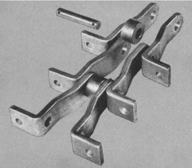
B. Chains and links. For trouble-free and long operation of grates, the grate bars should not be overheated and the chains should not elongate unduly over time. The differential elongation of chains is the cause of many grate problems, the most important being the breakages of long grate bars or T-bulb bars connecting the adjacent chains. The chains are usually designed to have tensility of about 32 T and forged construction with hardened rollers and pins (Figure 11.23).
|
TABLE 11.4 Typical Composition of Grate Casting
|
|
Note: For special applications and refuse firing, it is normal to employ ductile cast iron for the grate bars. |
|
FIGURE 11.23 Typical forged grate chain with hardened rollers and pins. |
C. Chain tensioning arrangement. This arrangement is not needed for chains with catenary design as it is self-tightening. It is required for chain-type grates to adjust the tension, making the grate taut as the chains elongate over a period. The tensioning is done by pulling the driven shaft away from the drive shaft.
D. Area to air. Approximately 6-10% of the total grate area should be for combustion air through the grate. More area for air is given in the grates of MB as almost all the air passes through the grate and excess air levels are high. Least area for air is given for spreader firing of biofuels.
E. Grate resistance to air. Grates offer a resistance of —40 mm wg. Normally, PA forms around 70-80% of the total air or a little above stoichiometric air with the rest as SA or OFA. Primary air is less for fuels with higher volatiles, such as lignite and biofuels.
F. Air seals. Front and rear seals confine air to the effective length of the grate, which is —500 mm smaller than the shaft centers. In chain type, where there are air compartments to vary air to different combustion zones, there are seal castings resting on the grate for sealing the adjacent compartments.
G. Air temperature limits are different for coal and biofuels.
I. In coal firing the limit is —160°C normally and 180°C at the extreme to prevent caking or coking of coals.
Ii. In biofuel firing a much higher 230°C temperature is limited by bearing lubrication considerations. For temperatures higher than 200°C alloy grate bars are usually considered.
H. Grate area. The length of the grate is governed by spreader throw and the width by the limiting torsional stress levels in stoker shafts as well as the ability to spread the combustion air across the grate. Catenary grates are limited to —4.87 m (16 ft) width with their small-diameter solid shafts and the chain type to —6.1 m (20 ft) with big hollow shafts. On the other side, grates as small as 2 m are also employed.
I. Spreaders. From considerations of redundancy, two spreaders are the minimum. Spreaders can distribute fuel over 1-1.5 m width. The maximum number of spreaders can be as high as eight to cover a width of —12 m.
J. Stoker drives can be mechanical or hydraulic. In terms of initial and running costs, both power consumption and reliability are about the same.
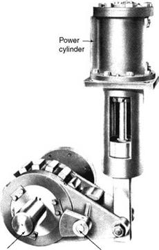
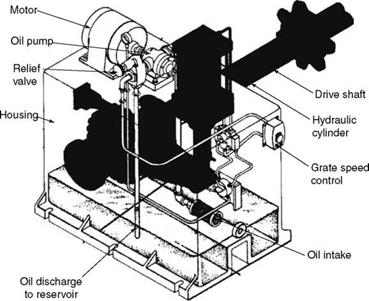
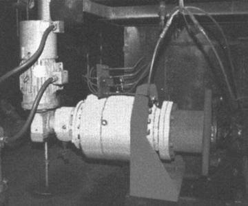
K. With the use of a pawl and ratchet arrangement (Figure 11.24) hydraulic drives (Figure 11.25) are in a position to reverse the grate to free a jam.
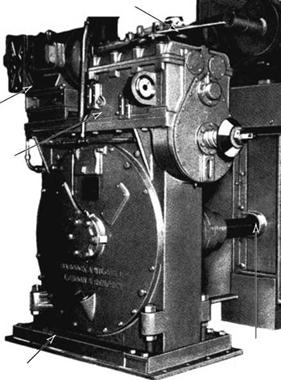
L. Mechanical drives cannot reverse the grate because of the worm and wheel (Figure 11.26). It is possible with a planetary gear system (Figure 11.27).
M. In principle, mechanical drives are better for the life of chain, as there is no alternate tension and relaxation. In a hydraulic drive, with every stroke of the piston, the tooth of the pinion mounted on the drive shaft is rotated, thus stressing and relaxing the chains.
N. A worm gear arrangement is common in a mechanical drive, powered by a variable speed motor or a turbine. This is a rugged system but occupies valuable space at stoker front.
O. A planetary gear box with a variable speed motor is a new arrangement with the advantage of great compactness as the box is small and shaft-mounted.
|
Output shaft Pawl and Ratchet Arrangement |
|
FIGURE 11.24 Pawl and ratchet in hydraulic power pack.
|
|
|
|
|
|
|
|
|
|
|
FIGURE 11.26 Mechanical drive—worm and wheel.
|
P. Hydraulic drives are also rugged and trouble-free. The space occupied is about the same as for a worm gear arrangement and larger than the planetary gear box.
Q. Grate speed should vary between 0 and 9 m/h to cater to all sizes and fuels. Speeds of —6 m/h are required for high-ash coals. Higher speeds are for emergency evacuation of fuel. r. A shear pin or overload clutch is essential for safety of stoker.
S. Stoker reversing should be possible to relieve any jamming due to entrapment of foreign material in the chain mechanism.
11.4.1 Spreader Firing with Dumping Grates
Dumping grate stokers shown in Figures 11.28 and 11.29 are economical choices for biofuels such as bagasse for low and medium steam generation for the process industry.
Combustion Process on Dumping Grates
Spreader stoker combustion is very different from MB on TG stokers as elaborated in Section 11.4.1.1. By means of feeders and spreaders, the fuel is metered and distributed onto the burning fuel on the grate below. Unlike TGs, the DGs are stationary. Also the dimensions are smaller so that the fuel spread is more complete and uniform. During the flight, the high temperature of the furnace and the upward flow of hot flue gases help flash drying of the fuel and combustion of volatiles. Depending on the VM of fuel, 40-60% of combustion takes place in the furnace in suspension before the devolatilized fuel lands on the thin film on the active fuel bed or grate, where the FC of the fuel burns rapidly to complete the combustion, similar to the spreader firing on TG. Ash is intermittently dumped into the ash pit below in DG instead of the front ash pit in SS firing.
Design Aspects of Dumping Grates
• A minimum of two grates are required per boiler so that the steam generation is maintained, albeit at reduced rate, when ash from one section is dumped.
• Satisfactory fuel distribution requires a grate width of —1.5 m. Also, to spread the fuel in the front part, the grate length is between 4.5 (normal) and 5 m (maximum—effective). Moreover, this suits the manual tools required to tend the grate. Although the spreading pattern of the fuel is the same for DG and TG, the length
|
|
|
FIGURE 11.29 Dumping grate setting. (Detroit Stoker Company, U. S.A. With permission.) |
|
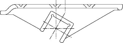
FIGURE 11.30 Typical grate casting for dumping grate. |
Of the TG can be higher because it moves toward the front and the fuel coverage of the entire grate is not necessary.
• Minimum length of a DG is —2.4 m, and the usual length increments are —225 mm, depending on the length of the grate castings as depicted in Figure 11.30.
• Each section has an independent fuel distributor.
• DGs cost less because the entire return strand of the TG and the drive system are avoided.
• Also the depth of the ash pit can be limited to —1 to 1.5 m, requiring practically no firing floor. The height of the boiler is thus lower.
• Because of the ash build-up on the grates, which impedes the combustion, the dumping grates are not suitable for coals with ash content exceeding —15%.
• Heat release rates for coal are 70% of the HRR of SS.
• Coal firing. For uniform spreading, the coal sizing requirements are stringent and fines create a lot of problems. Frequent ash discharges needed for proper combustion have the following disadvantages:
— At every dumping, green fuel is lost and overfiring of the running grates takes place, thereby reducing the efficiency and increased unburnt losses.
— The steam production from the boiler is somewhat uneven.
These limitations have more or less eliminated DGs from coal-fired markets.
• Bagasse firing. The DGs are attractive and economical, particularly for bagasse due to the following reasons:
1. The fuel has very little ash.
2. It is always uniformly sized.
3. It burns easily with high efficiency.
4. Low ash permits less frequent ash dumping (typically once a shift, and hence fewer losses and less overloading.
For capacities up to about 60-70 tph, the DGs are cheaper than TGs but are also slightly less efficient (Figures 11.28 through 11.30). Please refer to Table 11.5 for a comparison of DG and TG.
• Maximum combustion rates of biofuels for DGs are as follows:
— 2.5 MW/m2 or —2.17 X 10⁶ kcal/m2/h or 800,000 Btu/ft2 h with cold air
— 2.85 MW/m2 or —2.44 X 10⁶ kcal/m2/h or 900,000 Btu/ft2 h with hot air
|
TABLE 11.5 SS Firing on Dumping Grate versus Traveling Grate—A Comparison
|
Unlike with coal, suspension firing of biofuels in a furnace releases higher heats ranging from 40 to 60% and the burning of FC on the grate is lower. During the de-ashing periods, the running grates should not be loaded beyond 110% of the maximum rating. The other points are
• Turndown is about 3:1.
• Hot air temperature should be limited to a maximum of 200°C.
• The fuel feeders and distributors are common for both types of spreader firings.


 7 сентября, 2013
  admin
admin 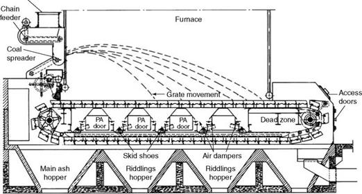

 Опубликовано в рубрике