The big stoker market today focuses on bagasse, wood, and biofuel firing, with coal firing having gone to the industrial boiler market. Bagasse-fired boilers for process and cogen have capacities as large as 250 tph and pressures reaching 130 bar and temperatures of 540°C. Similarly wood-firing in cold climates has been employing large stoker-fired boilers. Very large coal-fired boilers were built some 30 years ago when the quality of coals was better and the environmental rules were not so stringent. With the advent of FBC, this market has practically disappeared, with stoker firing considered only when the biofuels are to be burnt alone or in combination with coal.
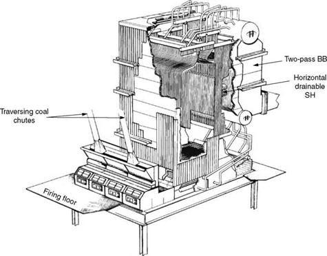
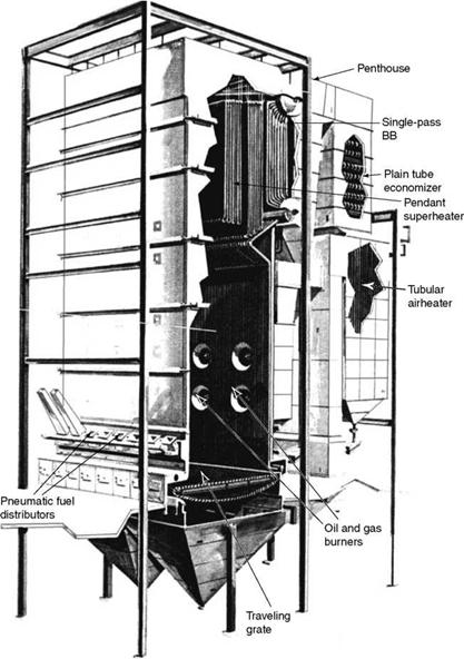
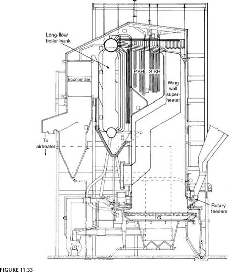
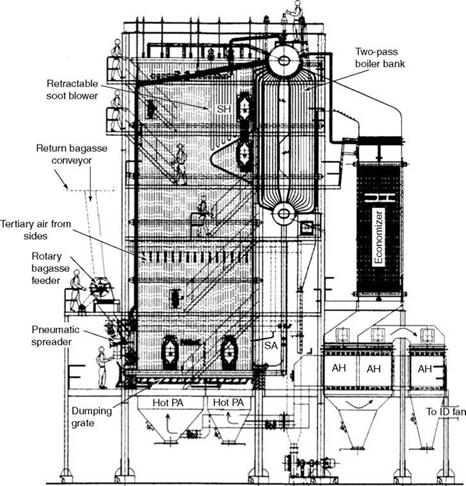
Some examples of stoker-fired boilers are shown in Figures 11.31 through 11.34.
|
FIGURE 11.31 MB gravity-fed TG with drainable superheater and boiler. |
|
FIGURE 11.32 Wood waste and oil — or gas-fired single-pass boiler bank. |
Figure 11.31 depicts an MB stoker-fired boiler with TG and gravity feeding. Normal height of the firing floor is —5 m. Coal is fed by traversing chutes and ash is discharged at the rear. The superheater (SH) is horizontal and drainable.
In Figure 11.32, a TG with spreader firing and front ash discharge is shown. It is a multifuel-fired boiler with oil and gas fired from the rear as there is space on the rear side due to a single-pass BB. It is a catenary-type stoker with front discharge and pneumatic distributors for fuel spreading. The SH is vertical pendant and nondrainable.
Figure 11.33 shows a large boiler built some 30 years ago. Lignite was the fuel. A longitudinal BB was employed. It was for power generation and it generated —300 tph.
|
One of the largest SS lignite-fired boilers (~300 tph for 80 MW with 2 X 19 ft X 27 ft [2 X 5.8 m X 8.23 m] long grate). |
Oil or Gas Firing in Stoker-Fired Boilers
• The preferred location for burners is the rear wall, unless blocked by a long BB, as there is usually ample furnace depth to accommodate the flames, and the resulting gas temperature entering the SH zone is more uniform.
• Burners can also be located on a side wall as a second preference as the gas entering the SH zone is not uniform, provided there is enough clearance for flames. The number of burners may have to be increased when the furnace width cannot accommodate the flame length.
• The lower burner should not be < ~2.2 m from the top of the grate to prevent overheating of the grate bars.
• Flame monitors should be carefully chosen to prevent interference from the stoker flames from below.
• For an extended duration of burner usage, the grate air damper should have a crack opening all the time so that a small air leakage is intentionally provided for cooling the grate and preventing its overheating.
• A separate FD fan for burners may be provided instead of depending on the main fan, as the pressure of air required for the burners is much higher at 150-200 mm wg (depending on the turndown) as compared with —40 mm for the grates.
• Superheater surface requirements are governed by oil firing, as the gas generated is 15% lower than that for coal.
• Spacing of tubes in convection passes is usually more than that required if solid fuel was burnt alone. This is because of the sticky deposits left on the tubes by the oil, particularly the heavy oils.
Principles of Spreader Stoker-Fired Boiler Design
The following points explain the steps involved in the design of an SS-fired boiler:
• The design begins with the sizing of the stoker and the selection of the feeders for the amount of fuel to be burnt. The grates are available in certain sizes and usually the feeders are limited to one or two sizes. Permissible grate HRR determines grate area. Usually, as the boiler sizes increase, accommodating the required number of feeders governs the grate width more than the HRR.
• Furnace sizing follows the sizing of firing equipment. Residence times (Table 6.1) and the rates of volumetric releases for the fuel decide the furnace volume. See Chapter 2. If auxiliary fuels such as oil and gas are used, the volume has to be suitably altered. Furnace arches are used for MB whereas two or three levels of SA are used for SS firing for coal and biofuels, respectively.
• Furnace sizing is the most important part of the boiler design, as it determines the cost of the boiler. It also decides the drum length and size of the convection bank and the back-end equipment. It is better to err on the conservative side in furnace sizing as there is no way of increasing the size at a later date. It is also an insurance against a possible variation in fuel properties in future.
• The furnace arch, above which the pendant SH is located, is usually placed between 3 and 8 m above the grate, depending on the boiler size. Arch depth is varied between 30 and 70% of the furnace depth, depending on the number of SH coils to be placed above. It is inclined at no less than 30° to horizontal, from a circulation point of view, to avoid possible overheating due to steam formation.
• Platen SH hanging in the furnace is required only when steam temperatures are —500°C or more. For all the other cases, a pendant SH can be accommodated above the arch. Access, spacing of coils to avoid fouling, soot blower location, tube supports, sealing with roof tubes, tube bending, tube expansion, metallurgy, etc. are to be carefully considered based on previous experience and manufacturing capabilities. The fuel properties and firing methods also dictate possibilities.
|
SA fan FIGURE 11.34 DG grate boiler with 40 tph capacity. |
• Superheaters can be vertical nondrainable or horizontal drainable. The latter does
Not lend itself to higher SH.
• Superheaters are usually followed by BB if the pressures are < 70 bar (~1000 psig).
Boiler banks are usually modular. The choice of single — and two-pass BB is largely
Governed by the following considerations, although exceptions abound.
-Two-pass or longitudinal-flow or three-pass cross flow BBs go well with MB as the dust loading of the flue gases is low.
-Single-pass cross flow BBs are used for all fuels in spreader firing to avoid erosion of the BB tubes due to the gas turns of longitudinal flow.
-Two-pass bank in SS firing is employed only if the fuel is known to be nonerosive or for small boilers where gas loading per unit width is low.
-One or two-pass BBs are also decided by the layout advantages.
• The gases are to be cooled to < 450°C in the first boiler pass to permit plain steel casing in the second pass that houses the economizer (ECON) and airheater (AH). With BB this is normally achievable. At temperatures >450°C there is a fear of stagnation of water in the last tubes of the BB due to steam formation that upsets the circulation.
• The economizer is usually a plain tube and an in-line construction. Finned tubes and staggered arrangements can also be used if the flue gases are known to be benign with less dust load. Cast iron gills are the solution if the fuel has high S and feed temperature is on the lower side. Chapter 6 provides more details.
• Inclusion of an AH is mandatory for biofuels as the moisture in fuel has to be flash- dried. But the AH outlet temperature has to be within the permissible limits of the grates.
• For coal firing AH has to be avoided if possible as hot air has a tendency to promote caking and clinkering. Although this is possible in a process application with low feed temperatures, a cogen plant with high feed temperature makes it mandatory to have an AH to cool the gases to an acceptable limit. Airheaters in such case should be kept to a minimum.
• When both ECON and AH have to be provided, the choice must be optimize the costs. The cost of the ECON has to be compared with the cost of the AH only after its ducting cost is also added.
• Tubular AHs are the usual choices. Vertical tubular AHs are more popular.
The fuel flexibility should be evaluated from two considerations.
1. Simultaneous multiple fuel-firing capability or cofiring several fuels
2. Range of fuels that can be burnt
Stoker firing, particularly SS, is effective for multifuel firing capability. In stoker-fired boilers, the following features lend themselves to mounting multifuel-firing equipment.
• The grates located at the bottom
• Tall and vertical furnace walls uncluttered
• Large area
Oil and gas firing to 100% maximum continuous rating (MCR) usually poses no problem. On a large boiler, oil or gas on the side wall and waste gas on the opposite wall can be easily burnt. In SS, along with coal, one or two biofuels can be easily burnt by employing mechanical and pneumatic distributors. Instrumentation and control (I&C) for all these fuels can be satisfactorily hooked up. The sizing of fuels is, in most cases, easy and fuel feeding is simple.
The multifuel flexibility of SS is amazing. With smaller boiler sizes and small quantities of fuel, it is ideally suited for process industry. Co-firing capabilities of PF are limited, and it can be argued that in large utilities this may not be required. Co-firing in FBC boilers is also very limited. Even 100% oil firing may not be possible in many designs. In comparison, all types of stokers score high.
Range of Fuels
The variety and range of fuels that can be burnt are also very impressive, particularly with SS. Coals, lignites, nonabrasive solid fuels, and many sized biofuels (such as bagasse and rice husk) that are fit for spreading can be burnt. The main reason is the flight of the green fuel in a hot furnace and subsequent landing on top of the burning bed of fuel, helping the fuel to dry and ignite effortlessly. In SS solid fuels with GCV as low as 2000 kcal/kg, fuels with moisture as high as 52% and ash as high as 45%, coals with VM as low as 20% can be burnt. Even lower VM can be handled by sandwich firing.
However, stokers are no match to FBC for firing poor fuels. Admittedly the SS is far more versatile in comparison with the other grates due to the split combustion, that is, in suspension and on grate. But this is of no help in burning a variety of inferior fuels. The high moisture or high ash or poor volatiles or low heating value (HV) of many poor and unconventional fuels requires a big heating source and adequate time with turbulence to help them dry ignite and burn, in the form of a hot and turbulent bed of inert material in both bubbling fluidized bed combustion (BFBC) boilers and circulating fluidized bed combustion (CFBC) boilers. Fuels that have a GCV as low as 1400 kcal/kg are easily burnt in FBC. See Figure 12.9.
For biofuels, stokers are the only solution as these fuels in most cases are too light to stay in the bed and have no ash to replenish the bed material if they are to be fired in FBC. Fortunately they have no S to create SOX problems or appreciable N to have NOX issues, making them suited for uncontrolled stoker firing.
Biofuels, such as wood, wood wastes, bark, saw dust, bagasse, and so on, have been burnt in boilers for power and process for many decades. Burning a greater variety of biofuels is gathering momentum as
• The prime fuels are becoming more expensive.
• Biofuels are renewable and do not deplete the fossil reserves.
• The environmental norms are getting tighter. Production of CO2 is urgently needed.
• Biofuels produce no offensive levels of SOx and NOx.
Biopower cannot be produced in large quantities nor can it be present near big power consumers. As distributed power generation is gaining acceptance, it is strengthening the case in favor of biofuels. Distributed power is generation of power at several places in smaller amounts instead of a centralized single location.
There is no better option than stoker firing for meeting this emerging trend of burning biofuels. Thin pile burning on PHG is nearly as good if the ash is low and continuous ash discharge is not required. For very high-moisture fuels, pile burning (up to 60%) and semipile burning in IWCG (up to 70%) are the only alternatives. These are discussed in Chapter 9.
Biofuels are described in detail in Chapter 3. To briefly recapitulate
• They are fluffy and often stringy. Their bulk density is low, making them expensive to transport. This is the main reason for adopting distributed generation.
• For the same reason large quantities of fuel cannot be made available at a single location.
• Biofuels are seasonal. Also the availability is widely fluctuating with peaks and shortages. During low periods either a prime fuel such as coal or preferably another biofuel has to be made available. The boiler has to be multifuel fired.
• From the point of combustion, the following points are to be noted:
— The moisture of biofuels is quite high, varying from 20 to 70%. This calls for hot air for combustion to dry the fuel and help in ignition. Beyond —52% of fuel moisture, pile or semipile burning has to be adopted in place of SS firing or PHG. Pile burning is practically obsolete (see Chapter 9), IWCG is the present-day choice. The flame temperatures are low and NOx formation is also low.
— The VM is uniformly high, varying from 60 to 88% on a daf basis, helping to counteract the cooling effect of high moisture in fuel under ignition and combustion.
— There is a small amount of ash of 0.2-5.3% on a dry basis. The 15% ash in rice husk is about the maximum.
— The biofuels are practically free of sulfur (<0.1% elemental S), making combustion SOx-free.
— Fuel nitrogen is also low, further reducing the chances of NOX.
• Fuel transportation is usually by belt or slat conveyors. Feeding is by rotary or screw feeders. For low very fluffy fuels such as bagasse, the rotary feeders are universally adopted. Screw feeders are for fuels that do not pack.
There are two types of biofuels depending on the alkali content in ash.
1. Biofuels that have no appreciable amounts of alkalies in ash have high initial ash deformation temperature (IADT), which permits higher volumetric rates and furnace exit-gas temperature (FEGT), making it possible to generate high SH steam. Wood, bagasse, and rice husk belong to this category.
2. If high amounts of alkalies are present in ash, the FEGT has to be lowered well enough to prevent fouling of SH with corresponding lowering of furnace volumetric HRR. It is prudent not to attempt high superheater outlet temperature (SOT) as the fouling of convection banks can severely affect availability.
Table 11.6 indicates the limits in furnace sizing for the two types of biofuels. Boiler design for biofuels should have the following features to provide efficient combustion:
• Fuel sizing must be understood carefully before choosing the type of grate. Firing equipment should be a DG or SS for sized fuels with moisture <52%, which can be
|
TABLE 11.6 Furnace Sizing for Biofuels
|
Spread on the grate. For unsizable or stringy fuels, the RG is a better choice as it is gravity fed. If there is more moisture, such fuels are burnt via pile burning.
• If coal firing is to be done with any biofuel, SS is the only choice. This is often required in cogen.
• For moistures up to 70%, IWCG is used for larger capacities of even 200 tph or thick pile burning for small capacities of ~20 tph. Furnace arches are essential for reradiating the heat. Oil support is provided to help start up and load stabilization.
• AH is needed to drive off moisture. Air temperature can be as high as the grate can bear—~230°C for TG and ~200°C for RG. PHG and IWCG are better as they can take higher temperatures of ~315°C. Many times AH is designed for 80% air passing through it as biofuels need nearly 30% OFA for which cold air is used.
• High VM requires more air and it is normal to provide 30% OFA. In addition to SA in front and rear walls to the extent of 20%, TA of ~10% is provided nearly 2 m below the nose, usually in side walls to trap and burn the fines. The TA acts as an air curtain and usually the air nozzles are smaller and more in number. But this aspect is fuel-specific.
-The requirement of low FEGT due to high alkalies makes the furnace volume high. This reduces the carryover of fuel char and ash due to their lightness, causing efficiency loss. The resulting volumetric HRRs appear low and residence times high.
-If there is cofiring, the FEGTs are to be even lower as the melting point of the ash eutectic is likely to be lower than the melting point of fuel ash.
• Higher fuel moisture creates larger flue gas quantities and smaller SH. For multifuel firing with coal, the SH size is governed by the coal and the attemperator by the biofuel with maximum moisture.
• The chances of fouling of the final SH are high and may call for a retractable soot blower (SB) for effective cleaning.
• Grate HRR, furnace ratings, and gas velocities are discussed in Chapter 6.
• Also, refer to Section 9.2.1.5 for details on pile burning.
• Dust capturing equipment needs a careful selection based on the specific biofuel and permissible particulate emission level due to the lightness of the particles and high resistivity. Depending on the gas velocities and furnace and grate loadings, the fly ash can be as high as 80% of the total ash. Typical dust load at the entry to the dust-collecting device varies from 2.5 to 8 g/N m3, depending on the ash content and the firing equipment—MB or SB.
• Fly ash produced is very fine and not satisfactorily trapped in mechanical dust collectors (MDCs). On contact with the cyclone walls, the ash tends to break down into very fine powder and gets partially carried away with the gases.
• Electrostatic precipitators (ESPs) are not satisfactory as the ash resistivity is high.
• Bag filters are effective but there is a danger of fire as the burning char can travel all the way to the FF. It is usual to have a knock-out baffle to change the gas direction so that the char and ash can precipitate out of the gas stream.
• Wet scrubbers are also used but the power costs are high. Air pollution becomes a water pollution issue and unless there is a proper way out of that, wet scrubbers cannot be adopted.
Further Readings
Graham, J. D., 1984, Biomass fuels for steam generation, B&W Canada, presented to American Power Conference, April.
Industrial boilers—What’s happening today? February 1977.
Johnson, N., Fundamentals of stoker fired boiler design and operation, Detroit Stoker Co and SFT, July 15-17, 2002.
Magassiner, N., van Alpen, C., Inkson, M. B., and Misplon, B. J., Characterising fuels for biomass-coal fired cogeneration, Thermal Energy Systems.
Magassiner, N., Bagasse fired boilers with reference to cogeneration, Thermal Energy Systems.
Makansi, J., 1987, Co-combustion—A special report, Power, July.
Morrow, R. S., Renewable fuel grate firing technology—The European experience, Detroit Stoker Co.
Schwieger, B., 1980, Power from wood—A special report, Power, February.
Schwieger, B., 1975, Power from waste—A special report, Power, February.
Smith, A. D., 1973, Bark burning, Foster Wheeler Limited, Technical paper T290 presented to Canadian Pulp and Paper Association, March.
Smith, A. D., 1976, Wood as a fuel, Foster Wheeler Limited, May.
Toupin, K., Modern wood fired boier designs—History and technology changes, DB Riley Inc., August 21-24, 1995.


 8 сентября, 2013
  admin
admin 


 Опубликовано в рубрике