Steam is used in (1) many processes for mainly heating and (2) many ways for power generation. Its utility is both in process industry and power plants. In the process industry it is produced for
1. Industrial processes involving mainly heating, steam drives, and other functions
2. Cogeneration (cogen) to provide other forms of energy, mainly power
In power plants it is generated for
1. Captive power for use by large cement, steel, aluminum, and allied plants
2. Grid power to feed the electricity networks for public distribution
Steam is
1. Produced in boilers at a high pressure
2. Expanded in turbines or drives or consumed by processes at a lower pressure
3. Condensed in processes or condensers to revert to water
4. Returned to the BFPs to be pressurized and fed to the boiler again
There is, thus, a cycle established between steam generation and condensate return. This steam cycle is one of the several thermodynamic or heat engine cycles used in diesel engines and gas turbine (GT) cycles.
Sadi Carnot was the first to introduce the concept of cycle along with reversible processes. See Figure 2.43. The cycle is applicable to any working fluid such as steam and gas. It is represented in chart form in Figure 2.44 and is called the ideal vapor cycle. Here heat is added and rejected at constant temperatures, with expansions and compressions carried out at constant entropies. The Carnot cycle offers the maximum thermodynamic or cycle efficiency between the temperatures of source and sink and is represented by the net work output/total heat input (Figure 2.44). In the T-s diagram it is calculated as
Cycle n = 1 — T (2.34)
T1 T2
Where T1 and T2 are the absolute temperatures of the source and sink, respectively.
The Carnot cycle cannot be replicated in practical world as the processes are reversible and frictionless and adiabatic. But the efficiency determined between heat and sink can represent the maximum to which the other cycles can be compared.

|
Heat input |
![]()
|
Power Output |
![]()
|
FIGURE 2.43 Carnot cycle in diagrammatic form. |
![]() The Rankine or steam cycle has already been introduced, and the salient points are briefly covered in Section 2.2.5. This cycle as applicable in condensing and cogen power modes is illustrated in Figures 2.45 and 2.46. With nearly 50% of heat rejection in the condenser, the cycle efficiency is —40% on NCV basis for conventional power plants with subcriti — cal steam parameters. With SC conditions the efficiency can go up to 42-43% and with
The Rankine or steam cycle has already been introduced, and the salient points are briefly covered in Section 2.2.5. This cycle as applicable in condensing and cogen power modes is illustrated in Figures 2.45 and 2.46. With nearly 50% of heat rejection in the condenser, the cycle efficiency is —40% on NCV basis for conventional power plants with subcriti — cal steam parameters. With SC conditions the efficiency can go up to 42-43% and with
|
FIGURE 2.44 Carnot cycle on T-s chart. |
|
FIGURE 2.45 Simplified steam cycle for power generation with condensing turbine. |
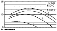
Ultracritical conditions, up to 44-45%. With regenerative feed heating, the thermal/cycle efficiencies increase significantly as the graphs of Figure 2.47 depict. More FWHs mean higher feed temperatures and cycle efficiency. Practical considerations limit the FWHs as shown in Figure 2.47. The optimum feed temperature rise is generally around 40°C for each FWH.
The cogen cycles, on the contrary, are far more efficient as there is no loss of heat in condensers. Depending on how much of heat is fully consumed in the process, the cycle efficiencies can easily reach 85%.
• Unlike the vapor cycle of Rankine, this is a gas-based cycle.
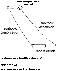
• While the expansion and compression parts of the cycle are isentropic as in the Rankine method the heating and heat rejection parts are at constant pressure and not at constant temperature, that is, isothermal.
• Heat rejection is to the atmosphere and there is no condensation.
• Recycling of working fluid is with reference to atmosphere.
Air, drawn from atmosphere, is compressed to high pressure when fuel is injected and burnt at constant pressure. The resulting hot gases are expanded in a GT, and the emanating cooled gases are rejected to atmosphere that acts as a sink. Figures 2.48 and 2.49 depict the cycle on T-s and P-v charts, respectively, and it is shown in diagrammatic form in Figure 2.50.
Open-cycle operation of GT with exhaust gases rejected to atmosphere, with no HRSG to recover heat, works with the Brayton cycle. With a lot of heat rejection the operation is not efficient. Combined cycle (CC) operation is a preferred solution, unless the fuel is very reasonable.
A Brayton cycle superimposed over a Rankine cycle is the CC. The exhaust of the GT is used for steam generation in HRSG, which runs a steam cycle with a condensing turbine. Naturally this is the most efficient of all cycles.
|
FIGURE 2.46 Simplified cogeneration cycle with back-pressure turbines. |
|
|
|
Feed water temperature rise (°C) |

|
60 100 200 260 |
 FIGURE 2.47
Improvements in cycle efficiency due to feed water heating by regeneration.
|
Entropy (s) FIGURE 2.48 Brayton cycle on T-s diagram. |
|
Heat input
|
|
Constant-pressure Heating To atmosphere Specific volume (V) FIGURE 2.49 Brayton cycle on P-V diagram. |
 FIGURE 2.50
Components of Brayton cycle.
A combined cycle for power generation is depicted diagrammatically in Figure 2.51. The CC can also be for cogen and is popular with process industries requiring steam in addition to power. Usually a back-pressure turbine takes the place of the condensing turbine to supply steam at the desired conditions.
Combined cycle power plants (CCPPs) have grown dramatically in size and efficiency in the past two decades. The present efficiencies on NCV bases are in excess of 55% with large GTs and approach 60% in the largest configurations. In the cogen mode the efficiencies are much higher.
|
FIGURE 2.51 Components of combined cycle. |
Further Readings
Marks’ Standard Handbook for Mechanical Engineers.
Perry’s Chemical Engineers Handbook.
Pratt, A. D., 1965 reprint, Principles of Combustion in Steam Boiler Furnace. B&W Limited, London. Steam: Its Generation and Use.


 19 августа, 2013
  admin
admin 


 Опубликовано в рубрике