Valves, mountings, and fittings are the auxiliaries in the steam and water circuit. The mountings and fittings are the mandatory safety devices specified by codes for permitting a boiler to steam. These are
• Main steam stop valve (MSSV)
• Nonreturn valve (NRV) on steam line
• Safety valves (SV)
• Blow-down valves
• High-low water-level alarms on steam drum
• Water-level indicators (WLI) on steam drum
• Pressure gauges on steam drum and SH
Valves on a boiler are mainly for start-stop service of steam and water. Control valves (CVs) are only for regulating the main FW and attemperator spray water. There is no direct regulation of steam in any boiler for output control, which is carried out only by regulating the FW. However, CVs are at times employed in steam circuits in applications such as drum attemperators where three-way CVs are used for dividing steam into the attemperator and bypass lines. Butterfly CVs are employed for larger sizes. Boiler valves are pressure valves and are governed by various ANSI or equivalent codes as listed below:
ANSI B16.5 for steel pipe flanges and flanged fittings
ANSI B16.11 for steel socket welding fittings
ANSI B16.25 for butt-welding ends (for pipes, valves, flanges, and fittings)
ANSI B16.34 for steel valves (flanged and butt-welding ends)
There are valves in oil and gas circuits for control and isolation functions, which are different in construction. Along with burner front piping, these oil and gas valve trains, mounted on suitable racks, are usually supplied by burner manufacturers. Ball, plug, and butterfly valves dominate oil and gas lines unlike the GGC valves (explained in the following text) in steam lines. Boiler steam and water valves can be classified into three types by construction.
1. Isolating valves form the bulk of boiler valves and are known as GGCs:
A. Globe valves
B. Gate valves
C. Check valves
Dictated by the process-flow conditions.
2. Control valves are governed by both process and control considerations.
3. Safety and blowdown valves are specific to a boiler.
Forged steel valves. Valves of 50 NB size and below are of forged steel construction, and size is amenable to drop forging. Even larger valves are available in forged construction but are more expensive than cast steel valves. Forged steel valves, being denser in structure, have thinner sections and hence are lower in weight. Their higher cost, particularly in larger sizes, is many times justified, as the compact size and lower weight allow flexibility and shorter routing.
Butt-welded socket-welded, and flanged ends. Small forged steel valves of 50 NB and below are made with ends suitable for socket welding. For larger sizes, the valves are made with either flanged or welded ends, with the latter type most common. The leakage aspect is totally taken care of with butt-welded valves. They are also lighter, thus helping in flexibility. Flanged valves are preferred in some applications, particularly at low pressures.
Major valves have long delivery times and constitute nearly 80% by value:
• MSSV and NRV
• Feed stop and check valves
• Start-up vent and its isolating valves
• SVs on drum, superheater (SH), and reheater (RH)
• Continuous blow-down (CBD) and intermittent blow-down (IBD) valves
• Main, low-load, and start-up feed CVs and their bypass and isolation valves
• Attemperator control and isolating valves
• Circulating pump’s isolating valves in water circuit on either side of the pump
In a variable-pressure boiler, the MSSV is not present but is merged with the main turbine inlet stop valve and located at the turbine end.
In HRSGs that have high pressure (HP), intermediate pressure (IP), and LP, the valves are repeated for each circuit. A large HRSG with 3P and RH is a veritable maze of valves of numerous types, sizes, and ratings.
Constructional features and prominent characteristics of the major boiler valves are briefly described in the following sections.
Main Steam Stop Valve and Nonreturn Valve
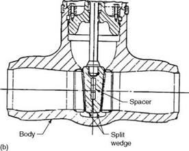
A boiler MSSV is a heavy-duty isolating gate valve matching the NB of main steam line or a size smaller, with minimum pressure drop. It can be a wedge gate, parallel slide, or Venturi type (Figure 8.44).
• Wedge gates are preferred for low and medium pressures but not for large sizes to limit the forces on the disk. The tapered faces of the disk provide a positive sealing.
• Parallel slides have two disks forcing themselves on the two faces by means of a set of springs to provide sealing. But the real sealing force is exerted by the upstream steam pressure on the disk. The thin disks are more flexible and can withstand more temperature and pressure than gates but are costlier and demand more maintenance.
• In Venturi construction, the valve body has taper at inlet and outlet so that the actual sealing disk has smaller diameter than the parallel slide valves. Venturi is preferred for very large sizes, although more expensive to make and maintain, mainly to reduce
• Pressure losses in valve
• Maintenance caused by larger mating surfaces of disks and seats
Usually, MSSVs are motorized and butt welded, but in smaller low-pressure process boilers, they can be hand operated and flanged. It is normal to have an integral body
|
|
|
FIGURE 8.44 (a) Typical parallel slide and (b) wedge gate valves. |
 Bypass valve of 15-25 NB (1/2 or 1 in.) size for pressure equivalization upstream and downstream to permit easy opening of MSSV for sizes of 150 NB (6 in.) and larger. Motorizing of bypass valve and interlocking it with the main valve are common for large high-pressure boilers.
Main steam stop valves vary a great deal in size, from —80 NB (3 in.) in small-process boilers to 600 NB (24 in.) or more in large utility boilers. The metallurgy, likewise, varies a lot from CS for steam temperatures up to —450°C (842°F) to 1M, 2M, and 9% Cr AS for temperatures up to —600°C (1112°F). ASTM specifications for CS castings and forgings are SA 216 WCB and SA 105, respectively. For cast AS, they are SA 217 WC6, WC9, and C12, whereas for forged steels, they are SA 182 F11, F22, and F91. For ss, it is SA 351 CF8M, whereas for castings and forgings, it is SA 182 Gr F316.
The sealing of a valve is achieved by bolting of the bonnet or by pressure sealing the parallel and wedge gate valve from inside as shown in Figure 8.44. Pressure seal construction is a more positive way of sealing, and it is smaller and lighter because the internal pressure is used for sealing. But it is sealed for life unlike the bolted construction, which permits inspection and access of valve internals when required. Pressure sealing is adopted for higher pressures.
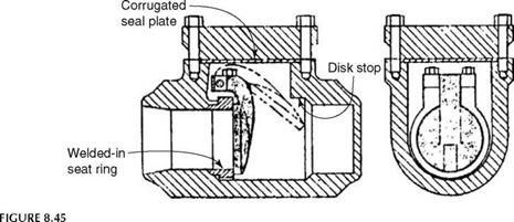
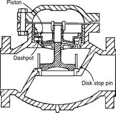
A nonreturn valve in the main steam line is of swing-check design to limit the pressure drop (Figure 8.45). It is of the same size as MSSV. In the feed line, however, it is usually the lift-check valve (Figure 8.46), as more pressure drop is permissible. Sometimes the feed stop and check valves are combined into a screw-down NRV (SDNR). Metallurgy of NRV on steam lines is usually the same as that of MSSV. In the FW lines, it is normally CS.
|
Typical swing-check valve. |
|
|
FIGURE 8.46
Piston check valve with dashpot.
These valves, located on the start-up vent line just ahead of MSSV, are motorized globe valves used during the boiler starting. The vent line, leading to the atmosphere, is opened at the boiler startup for
• Inducing part steam flow (25-50%) in the SH so that the SH tubes can be kept cool with steam flow
• Raising the steam temperature rapidly to the desired range for admission into the turbine
The vent line is closed once the steam is admitted into the turbine. A globe valve that can permit a large pressure drop across itself is adequate. The material of construction of the start-up valve is usually the same as that of the MSSV.
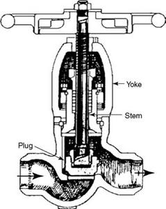
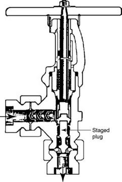
Blow-down and IBD valves are used for continuously controlling the silica in steam drum and periodically disposing of the sludge from bottom drum/headers, respectively. Therefore, the construction of the two valves is entirely different. The CBD valves are micrometer valves, that is, globe valves with elongated plugs, amenable to fine control and motorization. The IBD valves are usually quarter-turn quick-opening valves with high lift to permit effective flushing of sludge. Both CBD and IBD valves operate at the saturation temperature and are made of CS (Figures 8.47 and 8.48).
Safety valves are the most critical from the view of safety. Naturally, the boiler codes set fairly stringent norms for selection, sizing, and approval of these valves. There are three types of valves for pressure-relieving duties, as per ASME BPVC on equivalent codes. All are actuated by the upstream static pressure.
1. Safety valves are characterized by full and instant lift from the seat to permit full — steam relief on crossing the set pressure. These valves are used in vapor and gas service.
2. Relief valves have progressive lift (proportional to the overpressure). These valves are used in liquid service.
3. Safety relief valves can be used for water or vapor/gas service.
An SV is a glandless valve.
|
|
FIGURE 8.47
Hand-operated globe valve.
|
|
FIGURE 8.48
Typical IBD valve.
The following principles of sizing SVs are stated generally. The individual boiler codes contain exact rules and must be consulted for each case.
• The boiler and SH SVs should be so sized that the combined relieving capacity of all the valves should exceed the boiler evaporation.
• In WHRBs and HRSGs, the relieving capacity of the SVs should also adequately cover for the additional steam generation by the supplementary firing.
• Safety valves on SHs should be sized for 20-30% relieving capacity such that, with the flow through the SH, the tube metal temperatures stay within limits.
• Drum must be provided with at least two SVs.
• Safety valves on RHs should be sized for relieving the entire RH flow.
• For RH, most SVs are provided at the inlet due to the lower sizes resulting from a lower temperature. However, one or more SVs of not <15% RH flow are required at the outlet side to provide steam flow through the RH and prevent the tubes from overheating.
The blowdown and overpressure are the two parameters of the SVs that affect the boiler design pressure, which, in turn, affects the scantlings and boiler feed pumps (BFPs). There is a progressive reduction in both over the years.
• Set pressure of an SV is the pressure at which the SV pops open to relieve the pressure.
• High and Full lift SVs are two types classified by the lift of the valve. Full-lift valves have greater lift than high-lift valves. For the same size, therefore, the full-lift
Valve gives more discharge than the high-lift valve, thereby reducing the number of valves.
• Overpressure is the maximum attained by an SV when it is blowing. It is expressed as a percentage of the set pressure, and the codes define the permissible value. ASME limits set pressure to 3%. Other codes are known to permit even 10%.
• The codes define the limit for the reseating pressure after the blowing is complete. The difference between the reseating and the set pressures is called the blowdown of the valve. ASME limits blowdown to 2%. Other codes permit a variation as high as 10% for lower classes of SVs.
It is important to have a lower blowdown so that the boiler design pressure can be reduced, with the attendant lower thickness of the PPs and feed pump power. Note that the boiler design pressure is the highest drum SV lifting pressure determined by adding a margin over the sum of the SV blowdown and the drum operating pressure.
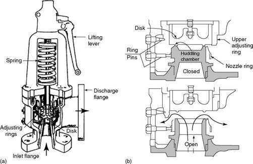
• Of the three types of SVs—spring-, torsion bar-, and pilot-operated, spring-operated SVs are the most popular (Figure 8.49a). The others have lower blowdown and are used in very large utility boilers.
• Safety valve design should ensure that the steam pressure at the discharge flange of the SV is <25% of the set pressure.
• Safety valves on the drum are of CS whereas those on SHs and RHs can be either CS or AS, depending on the temperature of steam to be relieved. Their relieving capacity for the same size is less, as the steam in the SH condition has greater specific volume.
• Safety valves require a great care in installation and operation. The seat and the disk should not be subject to scouring due to foreign particles lest the valve should leak.
|
FIGURE 8.49 Spring-type safety valves with valve and disk in open and closed positions. |
Hydrostatic plugs are to be placed at the inlet during any hydraulic test to prevent damage to valve internals due to the ingress of water. Frequent lifting of SV surely leads to leakages calling for boiler stoppage for seat lapping and reassembly.
• There are no glands in an SV, and all the internals are made from stainless steel with mirror finish to provide high-quality alignment and ensure accurate and perfect pop action while lifting and reseating. The SV blowing (and reseating pressures) and blowdown are set by the manufacturer in the presence of an inspector, and the rings are locked in position, requiring no further adjustment at site. Some valve designs have a provision for adjusting the blowdown at site by means of upper and lower adjusting rings, as shown in Figure 8.49b.
• Chatter of an SV is a repeated lifting and reseating of the valve caused mainly by faults in installation or a long inlet pipe or faulty discharge pipe system. The SV chatter inevitably leads to valve leakage, needing a lapping of the seating surfaces to restore the tightness.
• Spacing of SVs must be correct to prevent the discharge forces from interfering with each other.
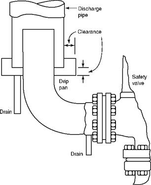
• Likewise, the discharge piping must be installed properly to lead the discharge steam safely to a suitable location, which is many times to the boiler roof. The discharge pipes or SV escape pipes are rigidly tied to any nearby boiler column, whereas the SVs located on drum or piping have their own thermal expansions. Suitable expansion chambers between the SV discharge elbow and the escape piping are essential to eliminate stresses due to differential expansion between the fixed escape piping and the moving SV. The expansion chamber should be provided with a suitable drain (Figure 8.50).
• Safety valve inlet nozzle length should be as short as possible to minimize the pressure loss, which can lead to chatter. SVs are usually directly mounted on drums or pipes. Pressure drop to the inlet has to be <50% of the SV blowdown. There is an upward force created as steam takes a turn inside the valve, which imposes stress on the drum and piping. To avoid the extra stress on PPs, the SVs can be located at some distance and rigidly supported on structural members. The inlet piping must be carefully sited and the set pressure of SV has account for pressure loss in the inlet pipe for a proper operation of the valves.
Electromatic SV. Considering the inevitability of SV seat leakage after a few lifts, it is a normal practice to install an additional electrically actuated SV on SH header, which operates first and prevents the main SVs from operating. This valve is provided with an isolating knife gate valve, which permits on-line maintenance. The discharge from this valve is not added to the relieving capacity of the other valves and is not covered by the boiler codes.
These valves form nearly 80% of the total. Sizes of 40, 50, 63.5, and, at times, 80 NB (1%, 2, 2%, and 3 in.) are used. Various designs and practical aspects of the drain and vent valves are briefly discussed below. At different locations, they have different roles to play.
• Carbon steel predominates except for draining and venting of the SH and RH where the drain and vent valves can be of CS or AS.
• Usually, the valves are made of the same material as the header to which they are attached.
|
|
FIGURE 8.50
Drip pan and safety valve in discharge piping.
• The drain valves of the water walls and ECONs must be firmly closed during the boiler operation and opened only for draining during shutdowns. These group of valves are always hand operated.
• The drain valves of the SH, RH, and SBs are normally motorized for operator’s convenience except in very small boilers.
• The vent valves are always motorized in medium and large boilers due to the remoteness of their location.
• Both drain and vent valves are of globe construction. Both experience high pressure drops and velocities, making them vulnerable to wear due to wire-drawing effect. For frequently operated valves, it is normal to provide a martyr valve of the same size and construction ahead of the main valve. The martyr valve is normally operated, whereas the main valve stays open, so that the martyr valve is sacrificed and main valve stays intact. When the martyr valve starts to pass, the main valve is operated until the next shutdown, and thus frequent boiler shutdowns are avoided.
• The drain and vent valves in ECONs and evaporator headers and the vents on the drum are mostly of 40 or 50 NB and SH drains, the final SH drain in particular, are larger.
• During startups, the final SH drain is used for inducing a flow through the SH to keep the tubes cool. Typically, they are sized for a flow of 10-15% MCR.
• Vent valves permit air escape so that pressurization of the boiler can begin. Air vents must have silencers of suitable size.
Control valves in a boiler are located only in the FW circuit and hence are low-temperature valves requiring CS. Attemperator spray CVs, dealing with not more than 10% of FW, are much smaller than feed CVs in a boiler, but of similar construction. Some codes insist on attemperator and its isolating valves and piping designed for the same conditions as the steam line on which they are mounted, assuming the worst case of steam flowing back to a closed attemperator line. AS valves of appropriate rating are then required. Single-seated CVs with low leakage are the normal choice.
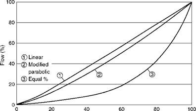
Control valve construction. Normal CVs can be considered as improved globe valves with definite flow versus pressure drop characteristics made possible by the special shape of the trim (valve and seat assembly). Flow characteristics are usually linear, equal percentage, and modified parabolic in which a unit change in lift produces a flow change of constant unit, constant percentage, or a combination of both, respectively. This is shown in Figure 8.51.
The trim is made of superior alloys to withstand erosion due to wire drawing, the cutting effect produced by high-velocity fluid stream resulting from a high pressure drop in the CV. Usually, the trim material is the martensitic ss to ANSI 420, which is machined and hardened to RC 43 to 47. Feed CVs (FCVs), in many cases, are required to generate low noise level, which is possible by reducing the fluid velocities inside the CV. Several valve trims are possible, some of which are shown in Figure 8.52.
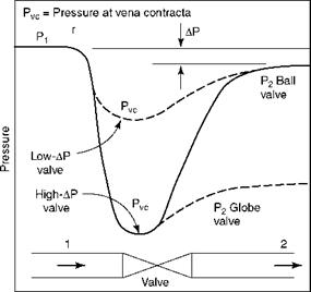
Cavitation needs to be avoided at all costs in the FCVs. When the liquid pressure drops abruptly and dips below the vapor pressure of the liquid at the vena contracta, bubbles are formed in the flow stream, which, on pressure recovery, collapse with great violence. The forces released on the collapse can cause serious damage to the valve and the seat, resulting in the formation of pits or cavities, with shortening of the life of the valve. This phenomenon with attendant forceful breakdown of the bubbles, is cavitation as shown in Figure 8.53. Cavitation is avoided by a progressive reduction of pressure in place of abrupt reduction and preventing low pressures at vena contracta that can induce formation of
|
Lift (%) FIGURE 8.51 Flow versus lift for various types of trims. |
|
|
|
Contoured trim |
|
Low-noise cage-guided balanced trim |
|
V-ported trim with balanced plug and ring |
|
Splined microflow trim |
|
FIGURE 8.52 Control valves with different trims. |
|
|
FIGURE 8.53
Pressure reduction and recovery in a flow stream.
Bubbles. Pressure recovery depends on the valve design. Ball and butterfly valves produce better pressure recovery than globe valves.
Control valve leakage. Seat tightness is an important feature of CVs and is classified according to ANSI B16.104 citing six classes of seat leakages ranging from 1 to 6 with increasing seat tightness.
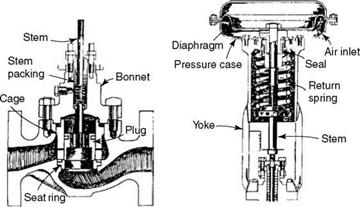
Control valve actuation. Diaphragm-operated CVs (Figure 8.54) for feed and attemperator are used in the normal mode of actuation. In large boilers when the required diaphragm size is too large, piston-operated valves are employed. For attemperator duty, diaphragm valves are adequate. The main FCV is usually pneumatically actuated, with an identical electrically actuated CV as a standby, ready to be pressed into service if the compressed air fails. In small boilers, a start-up feed valve of 10-15% capacity is provided parallel to the FCV for boiler filling and start-up duty. In medium and larger boilers, it is customary to have a separate boiler fill pump along with valves and have the low load running up to 30 or 40% MCR with low-load valves, which cut in and out automatically based on the flow.
|
FIGURE 8.54 Typical control valve and diaphragm actuator. |
|
C C |
FIGURE 8.55
Three-way mixing and diverting valve.
Control valve size. CVs are usually chosen one size lower than the line in which they are located for better controllability. There are gate valves for isolation both upstream and downstream for on-load valve removal for maintenance.
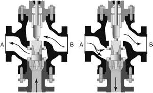
Three-way valves. In drum-type attemperator control, steam flow is divided between flow through drum and bypass, which is done by three-way CVs or a pair of butterfly CVs when the flows are larger. Three-way valves can be used for diverting or mixing duties as illustrated in Figure 8.55. Suitable trim is selected depending on the flow requirement.
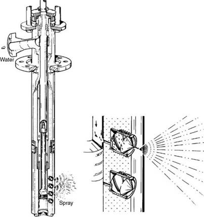
Attemperator spray CVs. Integrated attemperator CVs (Figure 8.56), combining the functions of the spray nozzle and CV, are used because the spray remains fine over the whole range of operation because of multiple nozzles that are brought into action one by one as the load increases. Since the water particles are very fine, there is no spraying in the thick pipelines; hence, there is a need for an SS sleeve downstream of the attemperator. The straight distance requirement of the steam pipe is also relaxed. The arrangement can be more compact, and the instrumentation also can be simpler. The turndown on steam side can be 10:1, whereas on water side, 300:1 gives a much wider range for operation.
|
FIGURE 8.56 Integrated attemperator spray control valve. |


 31 августа, 2013
  admin
admin 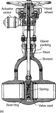

 Опубликовано в рубрике