7.1 Sizing flow meters; discharge coefficients for orifices, venturis, and nozzles; permanent pressure drop across flow meters; correcting steam flow readings for different operating conditions
7.2 Sizing orifices for water flow measurement
7.3 Sizing orifices for steam flow measurement
7.4 Significance of permanent pressure drop in flow meters; cost of permanent pressure drop across flow meters
7.5 Converting pitot tube readings to air velocity, flow in ducts
7.6 Sizing safety valves for boilers; ASME Code procedure
7.7 Relieving capacities for steam service; orifice designations for safety valves; relating set and accumulated inlet pressures
7.8 Selecting safety valves for boiler superheater; actual and required relieving capacities
7.9 Relieving capacities of a given safety valve on different gases
7.10 Relieving capacity of safety relief valve for liquid service
7.11 Determining relieving capacity of a given safety valve on air and steam
Service
7.12 Sizing control valves; valve coefficient Cv
7.13 Calculating Cv for steam service; saturated and superheated steam; critical
And noncritical flow
7.14 Calculating Cv for liquid service
7.15 On cavitation: recovery factors
7.16 Selecting valves for laminar flow
7.17 Calculating pressure loss in water line; determining friction factor for turbulent flow; equivalent length of piping; viscosity of water
7.18 Pressure loss in boiler superheater; estimating friction factor in smooth tubes; pressure drop in smooth tubing; Reynolds number for gases
7.19 Determining pressure drop under laminar conditions; pressure drop in fuel
Oil lines; effect of temperature on specific volume, viscosity of oils
7.20 Pressure drop for viscous liquids; friction factor under turbulent conditions
7.21 Calculating flow in gpm and in lb/h for fuel oils; expansion factors for fuel oils at different temperatures
7.22 Pressure loss in natural gas lines using Spitzglass formula
7.23 Calculating pressure drop of flue gas and air in ducts; friction factors; equivalent diameter for rectangular ducts; Reynolds number estimation
7.25 Determining flow in parallel passes of a superheater
7.26 Equivalent length of piping system; equivalent length of valves and fittings
7.27 Pressure drop of air and flue gases over plain tube bundles; friction factor for in-line and staggered arrangements
7.28 Pressure drop of air and flue gases over finned tube bundles
7.29 Factors influencing boiler circulation
7.30 Purpose of determining circulation ratio
7.31 Determining circulation ratio in water tube boilers
7.32 Determining circulation ratio in fire tube boilers
7.33 Determining steam flow in blowoff lines
7.34 Sizing boiler blowdown lines
7.35 Stack height and friction losses
7.36 Flow instability in evaporators
7.01a
Q:
How are flow meters sized?
A:
The basic equation for pressure differential in head meters (venturis, nozzles, orifices) is [1]
W = 359i’Qd02 (1a)
Where
W = flow of the fluid, lb/h
Y = expansion factor, which allows for changes in density of compressible fluids (for liquids Y = 1, and for most gases it varies from 0.92 to 1.0) Cd = a coefficient of charge do = orifice diameter, in. p = density of fluid, lb/cu ft p = ratio of orifice to pipe inner diameter = do/d,- h = differential pressure, in. WC
Cd may be taken as 0.61 for orifices and 0.95-0.98 for venturis and nozzles. It is a complicated function of Reynolds number and orifice size. The permanent pressure drop, Dp, across a flow meter is important, because it means loss in power or additional consumption of energy. It is the highest for orifices [2]:
TOC o "1-5" h z DP = h (1 — p2) (1b)
For nozzles,
1 — p2
DP = h ——- ^ (1c)
1 + p2
and for venturis it depends on the angle of divergence but varies from 10% to 15% of h. Q7.04 discusses the significance of permanent pressure drop and the cost associated with it.
7.01b
Q:
The differential pressure across an orifice of a steam flow meter shows 180 in. WC when the upstream conditions are 1600 psia and 900°F. The steam flow was calibrated at 80,000 lb/h under these conditions. Because of different plant load requirements, the steam parameters are now 900 psia and 800°F. If the differential pressure is 200 in. WC, what is the steam flow?
A:
![]() From Eq. (1a),
From Eq. (1a),
W / ^fph /
Where
W = steam flow, lb/h v = specific volume, cu ft/lb h = differential pressure, in. WC p = density, lb/cu ft
From the steam tables (see the Appendix),
Vj = 0.4553 cu ft/lb at 1600 psia, 900°F v2 = 0.7716 cu ft/lb at 900 psia, 800°F
|
80,000 /180 x 0.7716 _ j 235 |
![]() H1 = 180, h2 = 200, and W1 = 80,000. We need to find W2.
H1 = 180, h2 = 200, and W1 = 80,000. We need to find W2.
12
W2 V 200 x 0.4553
Determine the orifice size to limit the differential pressure to 100 in. WC when 700lb/s of water aT 60°F flOws in a pipe of inner diameter 18 in. The density of water is 62.4lb/cu ft.
Equation (1a) is not handy to use when it is required to solve for the orifice diameter do. Hence, by substituting for p = do/d,- and simplifying, we have
W = 359 CdYdf (2)
This equation is easy to use either when orifice Size is needed or when flow through a given orifice is required. The term l^/V 1 — p4 is a function of p and can be looked up from Table 7.1. Substituting for W = 700 x 3600, Cd = 0.61, Y = 1, p = 62.4, and h = 100, we have
700 x 3600 = 359 x 0.61 x 1 x 18V62.4 x 100 x F(p)
Or
F(p) = 0.45
From Table 7.1, by interpolation, we note that p = 0.64. Thus the orifice diameter do = 0.64 x 18 = 11.5 in.
What size of orifice is needed to pass a saturated steam flow of 26,480 lb/h when the upstream pressure is 1000 psia and line size is 2.9 in. and the differential is not to exceed 300 in. WC?
TABLE 7.1 F(P) Values for Solving Eq. (2)
Я F(Я) = Я2/V 1 — Я4
TOC o "1-5" h z 0.3 0.09
0.4 0.162
0.5 0.258
0.6 0.39
0.7 0.562
0.8 0.83
Using Eq. (2) and substituting Y = 0.95, p = 1/v = 1/0.4456 = 2.24lb/cu ft, and dt = 2.9, we have
W = 26,480
= 3 5 9 x 0.61 x 0.95 x 2.92 x F(p) x V2.24 x 300
Hence
F(p) = 0.58 From Table 7.1, p = 0.71. Hence do = 0.71 x 2.9 = 2.03 in.
What is the significance of a permanent pressure drop across the flow measurement device? 1.3 million scfh of natural gas with a specific gravity of 0.62 at 125 psia is metered using an orifice plate with a differential head of 100 in. WC. The line size is 12 in. What are the operating costs involved? Assume that electricity costs 20 mills/kWh.
The first step is to size the orifice. Use a molecular weight of 0.62 x 29 = 18 to compute the density. (The molecular weight of any gas = specific gravity x 29.) From Q5.03
P = 18 x 492 x———— ———— = 0.39 lb/cu ft
F 359 x 520 x 15 ‘
(A temperature of 60°F was assumed.) The density at standard conditions of 60°F, 15psia, is
492
P = 18 x—————- = 0.047 lb/cu ft
F 359 x 520 ‘
Hence mass flow is
W = 1.3 x 106 x 0.047
= 359 x 0.61 x 122 x V0.39 x 100 x F(p)
F(p) = 0.31
From Table 7.1, p = 0.55, so p2 = 0.3. The permanent pressure drop, from Q7.01, is
DP = (1 — p2)h = (1 — 0.3) x 100 = 70 in. WC The horsepower consumed in developing this head is
DP
HP = scfh x (460 + t) x————- (3)
P x 10′
It was assumed in the derivation of Eq. (3) that compressor efficiency was 75%. Substitution yields
70
HP = 1.3 x 106 x 520 x ———— — = 38
107 x 125
The annual cost of operation is
38 x 0.746 x 8000 x 0.02 = $4535
(8000 hours of operation was assumed per year; 0.746 is the factor converting horsepower to kilowatts.)
7.05
Q:
Often, pitot tubes are used to measure air velocities in ducts in order to compute the air flow. A pitot tube in a duct handling air at 200°F shows a differential of 0.4 in. WC. If the duct cross section is 4 ft2, estimate the air velocity and the flow rate.
A:
It can be shown [3] by substituting p = 40/(460 + t) that for a pitot,
V = 2.85 x Vh x (460 + t) (4)
Where
V = velocity, fps
H = differential pressure, in. WC t = air or flue gas temperature, ° F
V = 2.85 W0.4 x 660 = 46 fps
The air flow rate in acfm will be 46 x 4 x 60 = 11,040 acfm. The flow W in lb/h = 11,040 x 60 x 40/660 = 40,145 lb/h. [W = acfm x 60 x density, and density = 40/(460 + t).]
How are safety valves fOr boilers sized?
A:
The ASME Code for boilers and pressure vessels (Secs. 1 and 8) describes the procedure for sizing safety or relief valves. For boilers with 500 ft2 or more of heating surface, two or more safety valves must be provided. Boilers with superheaters must have at least one valve on the superheater. The valves on the drum must relieve at least 75% of the total boiler capacity. Superheater valves must relieve at least 20%. Boilers that have reheaters must have at least one safety valve on the reheater outlet capable of handling a minimum of 15% of the flow. The remainder of the flow must be handled by valves at the reheater inlet.
If there are only two valves for a boiler, the capacity of the smaller one must be at least 50% of that of the larger one. The difference between drum pressure and the lowest valve setting may be at least 5% above drum pressure but never more than the design pressure and not less than 10 psi. The range between the lowest boiler valve setting and the highest set value is not to be greater than 10% of the set pressure of the highest set valve. After blowing, each valve is to close at 97% of its set pressure. The highest set boiler valve cannot be set higher than 3% over the design pressure.
The guidelines above are some of those used in selecting safety valves. For details the reader should refer to the ASME Code [4].
7.7 Q:
How are the capacities of safety valves for steam service determined?
The relieving capacities of safety valves are given by the following expressions. ASME Code, Sec. 1 uses a 90% rating, whereas Sec. 8 uses a 100% rating [5].
W = 45 APaKsh (5a)
W = 50APaKh (5b)
Where
W = lb/h of steam relieved A = nozzle or throat area of valve, in.2
Pa = accumulated inlet pressure = Ps x (1 +acc) + 15, psia (The factor acc is the fraction of pressure accumulation.)
Ps = set pressure, psig
Ksh = correction factor for superheat (seE Fig. 7.1)
The nozzle areas of standard orifices are specified by letters D tO T and are given in Table 7.2. For saturated steam, the degree of superheat is zero, so
Ksh = 1. The boiler safety valves are sized for 3% accumulation.
Determine the sizes of valves to be used on a boiler that has a superheater. The parameters are the following.
Total steam generation = 650,000 lb/h Design pressure = 1500psig Drum operating pressure = 1400 psig Steam outlet temperature = 950°F Pressure accumulation = 3%
Superheater outlet operating pressure = 1340psig
The set pressure must be such that the superheater valve opens before the drum valves. Hence the set pressure can be 1500 — 60 — 40= 1400psig (60 is the pressure drop and 40 is a margin). The inlet pressure Pa = 1.03 x
1400 + 15 = 1457 psia. From Fig. 7.1, Ksh = 0.79.
W 130, 000 2
A =———— =————————— = 2.51 in.
45KshPa 45 x 0.79 x 1457
We used a value of 130,000 lb/h, which is 20% of the total boiler capacity. A K2 orifice is suitable. This relieves (2.545/2.51) x 130,000 = 131,550 lb/h.
The drum valves must relieve 650,000 — 131,550 = 518,450 lb/h. About
260,0 lb/h may be handled by each drum valve if two are used. Let the first
|
|
Valve be set at 1475 psig, or
Pa = 1.03 x 1475 + 15 = 1535 psia and the next at Pa = 1575 psia.
Area of first valve: A = —60,000 _ 3.76 in.2
45 x 1535
J, 260,000 2
Area of second valve: A =—————- = 3.67 in.
45 x 1575
Use two M2 orifices, which each have an area of 3.976in.2 Relieving capacities are
/3 976 3 976
776"+ T67~) x 260,000 = 556,000 lb/h which exceeds our requirement of 520,000 lb/h.
|
TAble 7.2 Orifice Designation
|
How is the relieving capacity of safety valves for gaseous service found?
The expression used for estimating the relieving capacity for gases and vapors [6] is
/MW
W = CKAPayj — (6)
Where
C = a function of the ratio k of specific heats of gases (Table 7.3)
K = valve discharge coefficient, varies from 0.96 to 0.98 Pa = accumulated inlet pressure = Ps(1 + acc) +15, psia Ps = set pressure, psig MW = molecular weight of gas T = absolute temperature, °R
A safety valve is set for 100 psig for air service at 100°F and uses a G orifice. What is the relieving capacity if it is used on ammonia service at 50°F, pressure being the same?
|
Table 7.3 Constant C for Gas or Vapor Related to Ratio of Specific Heats (k = Cp/C)
|
|
Source: Ref. 5. |
A:
Assume that k is nearly the same for both air and ammonia. Hence for the valve, CKAPa is a constant. For air, use C = 356, K = 0.98, A = 0.503, MW = 29, and T = 560.
Ffi29"
Wa = 356 x 0.98 x 0.503 x (1.1 x 100 + 15) J—-
A 560
= 4990 lb/h
(An acc value of 0.10 was used above.) From Eq. (6), substituting MW = 17 and T = 510 for ammonia, we have
29
|
A |
![]() X 510 = 1.246
X 510 = 1.246
Amm 17 x 560
Hence
4990
= 4006 lb/h
Amm
1.246
7.10a
Q:
How are the relieving capacities for liquids determined?
An expression for relieving capacity at 25% accumulation [5] is
Q = 27 . 2AKS (7)
Where
P1 = set pressure, psig Pb = backpressure, psig Ks = V 1/s, s being the specific gravity A = orifice area, in.2 q = capacity, gpm
7.10b
Determine the relieving capacity of a relief valve on an economizer if the set pressure is 300 psig, backpressure is 15 psig, and s = 1. The valve has a G orifice (A = 0.503 in.2).
A:
Using Eq. (7), we have
Q = 27.2 x 0.503 x 1 x V300 — 15 = 231 gpm
= 231 x 500 = 115,000 lb/h
At 10% accumulation, q would be 0.6 x 231 = 140 gpm and the flow W =
70,0 lb/h (500 is the conversion factor from gpm to lb/h when s = 1.)
7.11
Q:
A safety valve bears a rating of 20,017 lb/h at a set pressure of 450 psig for saturated steam. If the same valve is to be used for air at the same set pressure and at 100°F, what is its relieving capacity?
A:
For a given valve, CKAPa is a constant if the set pressure is the same. (See Q7.09a for definition of these terms.)
For steam,
20,17 = 50 x KAPa
|
/MW |
![]()
|
Hence |
![]()
|
20,017 KAPa = ————- = 400.3 A 50 |
![]() For air,
For air,
MW
W = CKAP„
T
C = 356, MW = 29, and T = 560°R for the case of air. Hence,
Wa = 356 x 400.3 x J-29 = 32,430 lb/h
V560
Q = 32,430 x 560 x——————- 15—————
* 0.081 x 492 x 465 x 60
= 244 acfm
(The density of air was estimated at 465psia and 100°F.)
7.12
Q:
How is the size of control valves for steam service determined?
A:
Control valves are specified by Cv or valve coefficients. The manufacturers of control valves provide these values (see Table 7.4). The Cv provided must exceed the Cv required. Also, Cv at several points of possible operation of the valve must be found, and the best Cv characteristics that meet the load requirements must be used, because controllability depends on this. For example. a quick-opening characteristic (see Fig. 7.2) is desired for on-off service. A linear characteristic is desired for general flow control and liquid-level control systems, whereas equal percentage trim is desired for pressure control or in systems where pressure varies. The control valve supplier must be contacted for the selection and for proper actuator sizing.
For the noncritical flow of steam (P1 < 2P2) [7],
^ W x [1 + 0.00065 x (t — O]
Cv = ——————- . :——————————————————- (8 )
V 2.11 x ^DP x Pt
|
Body size (in.) |
Port diameter (in.) |
Total travel (in.) |
Valve opening (% total travel) |
Km and Cf |
|||||||||
|
10 |
20 |
30 |
40 |
50 |
60 |
70 |
80 |
90 |
100 |
||||
|
3/4 |
1/4 |
3/4 |
0.075 |
0.115 |
0.165 |
0.230 |
0.321 |
0.448 |
0.625 |
0.870 |
1.15 |
1.47 |
0.70 |
|
3/8 |
3/4 |
0.120 |
0.190 |
0.305 |
0.450 |
0.628 |
0.900 |
1.24 |
1.68 |
2.18 |
2.69 |
0.80 |
|
|
1/2 |
3/4 |
0.235 |
0.400 |
0.600 |
0.860 |
1.16 |
1.65 |
2.15 |
2.85 |
3.40 |
3.66 |
0.70 |
|
|
1 |
1/4 |
3/4 |
0.075 |
0.115 |
0.165 |
0.230 |
0.321 |
0.448 |
0.625 |
0.870 |
1.20 |
1.56 |
0.80 |
|
3/8 |
3/4 |
0.120 |
0.190 |
0.305 |
0.450 |
0.630 |
0.910 |
1.35 |
1.97 |
2.78 |
3.68 |
0.70 |
|
|
1/2 |
3/4 |
0.235 |
0.410 |
0.610 |
0.900 |
1.26 |
1.80 |
2.50 |
3.45 |
4.50 |
5.36 |
0.70 |
|
|
3/4 |
3/4 |
0.380 |
0.700 |
1.10 |
1.57 |
2.36 |
3.40 |
5.00 |
6.30 |
6.67 |
6.95 |
0.75 |
|
|
11 /2 |
1/4 |
3/4 |
0.075 |
0.115 |
0.165 |
0.230 |
0.321 |
0.448 |
0.625 |
0.870 |
1.20 |
1.56 |
0.80 |
|
3/8 |
3/4 |
0.120 |
0.190 |
0.305 |
0.450 |
0.630 |
0.910 |
1.35 |
1.97 |
2.78 |
3.68 |
0.70 |
|
|
1/2 |
3/4 |
0.265 |
0.420 |
0.620 |
0.915 |
1.31 |
1.90 |
2.64 |
3.65 |
4.56 |
6.04 |
0.80 |
|
|
3/4 |
3/4 |
0.380 |
0.700 |
1.10 |
1.65 |
2.45 |
3.70 |
5.30 |
7.10 |
8.88 |
10.2 |
0.75 |
|
|
1 |
3/4 |
0.930 |
1.39 |
2.12 |
3.10 |
4.44 |
6.12 |
8.13 |
10.1 |
11.5 |
12.2 |
0.75 |
|
|
2 |
1/4 |
3/4 |
0.075 |
0.115 |
0.165 |
0.230 |
0.321 |
0.448 |
0.625 |
0.870 |
1.20 |
1.56 |
0.80 |
|
3/8 |
3/4 |
0.120 |
0.190 |
0.305 |
0.450 |
0.630 |
0.910 |
1.35 |
1.97 |
2.78 |
3.68 |
0.70 |
|
|
1/2 |
3/4 |
0.265 |
0.420 |
0.620 |
0.915 |
1.31 |
1.90 |
2.64 |
3.65 |
4.89 |
6.44 |
0.70 |
|
|
3/4 |
3/4 |
0.380 |
0.700 |
1.10 |
1.65 |
2.45 |
3.70 |
5.53 |
8.00 |
10.3 |
12.3 |
0.70 |
|
|
1 |
3/4 |
0.930 |
1.39 |
2.12 |
3.10 |
4.50 |
6.45 |
9.31 |
12.9 |
15.7 |
17.8 |
0.75 |
|
|
11 /2 |
3/4 |
0.957 |
1.45 |
2.31 |
3.70 |
6.05 |
9.86 |
15.2 |
20.2 |
22.0 |
22.0 |
0.79 |
|
|
3 |
1/4 |
3/4 |
0.075 |
0.115 |
0.165 |
0.230 |
0.321 |
0.448 |
0.625 |
0.870 |
1.20 |
1.56 |
0.80 |
|
3/8 |
3/4 |
0.120 |
0.190 |
0.305 |
0.450 |
0.630 |
0.910 |
1.35 |
1.97 |
2.78 |
3.68 |
0.70 |
|
|
1/2 |
3/4 |
0.265 |
0.420 |
0.620 |
0.915 |
1.31 |
1.90 |
2.64 |
3.65 |
4.89 |
6.44 |
0.70 |
|
|
3/4 |
3/4 |
0.380 |
0.700 |
1.10 |
1.65 |
2.45 |
3.70 |
5.70 |
8.66 |
12.3 |
14.8 |
0.65 |
|
|
1 |
3/4 |
0.930 |
1.39 |
2.12 |
3.10 |
4.50 |
6.70 |
9.90 |
13.2 |
17.9 |
23.6 |
0.65 |
|
|
11 /2 |
11/8 |
1.15 |
2.29 |
3.41 |
4.77 |
6.44 |
8.69 |
12.5 |
19.2 |
26.7 |
32.2 |
0.74 |
|
|
2 |
11/8 |
1.92 |
3.13 |
4.83 |
7.93 |
12.6 |
24.6 |
35.9 |
40.5 |
43.4 |
44.3 |
0.72 |
|
FIGURE 7.2 Typical control valve characteristics. |
For critical flow (P; > 2P2),
C W x[1 + 0.00065 x(t — Q]
V 1.85 x P1 ( 9
Where
T, ts = steam temperature and saturation temperature (for saturated steam,
T = ts)
W = steam flow, lb/h
Pt = total pressure (P1 + P2), psia
Q:
Estimate the Cv required when 60,000 lb/h of superheated steam at 900°F, 1500 psia flows in a pipe. The allowable pressure drop is 30psi.
A:
Since this is a case of noncritical flow, from Eq. (8), substituting t = 800 and ts = 596, we have
C _ 60,000 x [1 + 0.00065 x (900 — 596)] v = 2.11 x V30 x (1 500 + 1470)
= 114
7.13b
Q:
In a pressure-reducing station, 20,000 lb/h of steam at 200 psia, 500°F is to be reduced to 90 psia. Determine Cv.
A:
Use Eq. (9) for critical flow conditions:
20,0 x [1 + 0.00065 x (500 — 382)] co
V = 1.85 x 200 = 5
(382 is the saturation temperature at 200 psia.)
7.14
Q:
Determine the valve coefficient for liquids. A liquid with density 45 lb/cu ft flows at the rate of 100,000 lb/h. If the allowable pressure drop is 50 psi, determine Cv.
A:
The valve coefficient for liquid, Cv, is given by [8]
|
|
Where
Q = flow, gpm DP = pressure drop, psi s = specific gravity
From Q5.01,
W = 8qp
|
|
AP = 50
Hence
|
|
|
Cv = 278 x |
7.15
How is cavitation caused? How is the valve sizing done to consider this aspect?
Flashing and cavitation can limit the flow in a control valve for liquid. The pressure distribution through a valve explains the phenomenon. The pressure at the vena contracta is the lowest, and as the fluid flows it gains pressure but never reaches the upstream pressure. If the pressure at the port or vena contracta should drop below the vapor pressure corresponding to upstream conditions, bubbles will form. If the pressure at the exit remains below the vapor pressure, bubbles remain in the stream and flashing occurs.
A valve has a certain recovery factor associated with it. If the recovery of pressure is high enough to raise the outlet pressure above the vapor pressure of the liquid, the bubbles will collapse or implode, producing cavitation. High — recovery valves tend to be more subject to cavitation [9]. The formation of bubbles tends to limit the flow through the valve. Hence the pressure drop used in sizing the valve should allow for this reduced capacity. Allowable pressure drop APall is used in sizing,
|
(11) |
![]() DPall = Km (P! — rcpv)
DPall = Km (P! — rcpv)
Where
Km = valve recovery coefficient (depends on valve make) P1 = upstream pressure, psia rc = critical pressure ratio (see Fig. 7.3)
Pv = vapor pressure at inlet liquid temperature, psia
|
Cc U D.6——————————————————————————————— |
0.5 I————————————————————————————————————————-
0 500 1000 1500 2000 2500 3000 3500
VAPOR PRESSURE-PSIA
FIGURE 7.3 Critical pressure ratios for water.
Full cavitation will occur if the actual AP is greater than APall and if the outlet pressure is higher than the fluid vapor pressure. If the actual AP is less than APall, the actual AP should be used for valve sizing. To avoid cavitation, select a valve with a low recovery factor (a high Km factor).
How are valves selected for laminar flow and viscous liquids?
Calculate the turbulent flow Cv from Eq. (10) and the laminar Cv from [10]
/ 2/3
Lam Cv = 0.072 x ( AP j (12)
Use the larger Cv in the valve selection. (m is the liquid viscosity in centipoise.)
Determine the pressure loss in a 3in. schedule 80 line carrying water at 100°F and 2000psia if the total equivalent length is 1000 ft. Flow is 38,000lb/h.
The expression for turbulent flow pressure drop of fluids (Reynolds number >2100) is [11]
AP = 3. 36 x 10~6 x f W Le —t (13)
Where
AP = pressure loss, psi f = Darcy friction factor W = flow, lb/h
Le = equivalent length, ft (Q7.26 shows how the equivalent length can be computed) v = specific volume of fluid, cu ft/lb dt = tube inner diameter, in.
For water at 100°F and 2000 psia, from Table A4 (Appendix 3), v = 0.016. In industrial heat transfer equipment such as boilers, superheaters, economizers, and air heaters, the fluid flow is generally turbulent, and hence we need not check for Reynolds number. (Q7.24 shows how Re can be found.) However, let us quickly check Re here:
Re = 15 . 2 — (14)
D, m
Referring to Table 7.5, water viscosity, m, at 100°F is 1.645 lb/ft h
38,000
Re =15 . 2 X 29X645 = 121’070
The inner diameter of 2.9 for the pipe was obtained from Table 5.6. For turbulent flow and carbon or alloy steels of commercial grade, f may be obtained from Table 7.6. Here f for a tube inner diameter of 2.9in. is 0.0175. Substituting into Eq. (13) yields
AP = 3. 36 x 10~6 x 0. 0175 x (38,000)2 x 100 x = 6 . 6 psi
2 . 95
|
Temp (°F) |
Pressure (psia) |
|||||||||||
|
1 |
2 |
5 |
10 |
20 |
50 |
100 |
200 |
500 |
1000 |
2000 |
5000 |
|
|
1500 |
0.0996 |
0.0996 |
0.0996 |
0.0996 |
0.0996 |
0.0996 |
0.0996 |
0.0996 |
0.1008 |
0.1008 |
0.1019 |
0.1066 |
|
1400 |
0.0938 |
0.0938 |
0.0938 |
0.0938 |
0.0938 |
0.0938 |
0.0952 |
0.0952 |
0.0952 |
0.0961 |
0.0973 |
0.1019 |
|
1300 |
0.0892 |
0.0982 |
0.0892 |
0.0892 |
0.0892 |
0.0892 |
0.0892 |
0.0892 |
0.0892 |
0.0903 |
0.0915 |
0.0973 |
|
1200 |
0.0834 |
0.0834 |
0.0834 |
0.0834 |
0.0834 |
0.0834 |
0.0834 |
0.0834 |
0.0846 |
0.0846 |
0.0867 |
0.0926 |
|
1100 |
0.0776 |
0.0776 |
0.0776 |
0.0776 |
0.0776 |
0.0776 |
0.0776 |
0.0776 |
0.0788 |
0.0799 |
0.0811 |
0.0892 |
|
1000 |
0.0730 |
0.0730 |
0.0730 |
0.0730 |
0.0730 |
0.0730 |
0.0730 |
0.0730 |
0.0730 |
0.0741 |
0.0764 |
0.0857 |
|
900 |
0.0672 |
0.0672 |
0.0672 |
0.0672 |
0.0672 |
0.0672 |
0.0672 |
0.0672 |
0.0683 |
0.0683 |
0.0707 |
0.0846 |
|
800 |
0.0614 |
0.0614 |
0.0614 |
0.0614 |
0.0614 |
0.0614 |
0.0614 |
0.0614 |
0.0625 |
0.0637 |
0.0660 |
0.0973 |
|
700 |
0.0556 |
0.0556 |
0.0556 |
0.0556 |
0.0556 |
0.0556 |
0.0568 |
0.0568 |
0.0568 |
0.0579 |
0.0625 |
0.171 |
|
600 |
0.0510 |
0.0510 |
0.0510 |
0.0510 |
0.0510 |
0.0510 |
0.0510 |
0.0510 |
0.0510 |
0.0510 |
0.210 |
0.221 |
|
500 |
0.0452 |
0.0452 |
0.0452 |
0.0452 |
0.0452 |
0.0452 |
0.0452 |
0.0440 |
0.0440 |
0.250 |
0.255 |
0.268 |
|
400 |
0.0394 |
0.0394 |
0.0394 |
0.0394 |
0.0394 |
0.0394 |
0.0394 |
0.0382 |
0.317 |
0.320 |
0.323 |
0.335 |
|
300 |
0.0336 |
0.0336 |
0.0336 |
0.0336 |
0.0336 |
0.0336 |
0.441 |
0.442 |
0.444 |
0.445 |
0.448 |
0.460 |
|
250 |
0.0313 |
0.0313 |
0.0313 |
0.0313 |
0.0313 |
0.551 |
0.551 |
0.551 |
0.552 |
0.554 |
0.558 |
0.569 |
|
200 |
0.0290 |
0.0290 |
0.0290 |
0.0290 |
0.725 |
0.725 |
0.725 |
0.726 |
0.729 |
0.729 |
0.732 |
0.741 |
|
150 |
0.0255 |
0.0255 |
1.032 |
1.032 |
1.032 |
1.032 |
1.032 |
1.032 |
1.033 |
1.034 |
1.037 |
1.044 |
|
100 |
1.645 |
1.645 |
1.645 |
1.645 |
1.645 |
1.645 |
1.645 |
1.645 |
1.645 |
1.646 |
1.646 |
1.648 |
|
50 |
3.144 |
3.144 |
3.144 |
3.144 |
3.144 |
3.144 |
3.144 |
3.142 |
3.141 |
3.139 |
3.134 |
3.119 |
|
32 |
4.240 |
4.240 |
4.240 |
4.240 |
4.240 |
4.240 |
4.240 |
4.239 |
4.236 |
4.231 |
4.222 |
4.192 |
|
Table 7.6 Tube Diameter Versus Friction Factor (Darcy) for Turbulent Flow
|
7.17b
Q:
Estimate the pressure drop in a superheater of a boiler that has an equivalent length of 200 ft. The tube inner diameter is 2.0 in., the flow per pass is 8000 lb/h, the steam pressure is 800psia, and the temperature is 700°F.
A:
Using Eq. (13) and substituting v = 0.78 cu ft/lb and f = 0.0195 for turbulent flow from Table 7.6 (generally flow in superheaters, economizers, and piping would be turbulent), we obtain
6 2 0.78
DP = 3.36 x 10~6 x 0.0195 x 200 x 80002 x — = 21 psi
7.18a
Q:
How does the friction factor depend on pipe roughness?
A:
For smooth tubes such as copper and other heat exchanger tubes, f is given by [12]
F = 0.133 x Re~0,174 (15)
|
Dp v1826 N met „0.8267,0 .174 V —— = 0.0267 p m —■ Le a, |
![]()
|
Substituting this into Eq. (13) gives us |
![]() A n,-.0.8267 0.174 ’ /i /r
A n,-.0.8267 0.174 ’ /i /r
— = 0.0267 p m -31.174 (16)
(m is the viscosity, lb/ft h; V is the velocity, fps.)
7.18b
Q:
Determine the pressure drop per 100 ft in a drawn copper tube of inner diameter
1.0 in. when 250 lb/h of air at a pressure of 30 psig and at 100°F flows through it.
A:
Calculate the density (see Chap. 5):
45
P = 29 x 492 x———————— = 0.213 lb/cu ft
F 359 x 560 x 15 ‘
The effect of pressure can be neglected in the estimation of viscosity of gases up to 40 psig. For a detailed computation of viscosity as a function of pressure, readers may refer to Ref. 11. From Table 7.7, m = 0.047 lb/ft h. The velocity is
576
V = 250 x————————— = 60 fps
3600 x 3.14 x 0.213 F
AP 601826
— = 0.0267 x 0.2130 8267 x 0.0470174 x —1— = 7.7 psi
|
Table 7.7 Viscosity of Air
|
Q:
Derive the expression for DP for laminar flow of fluids.
A:
For laminar flow of fluids in pipes such as that occurring with oils, the friction factor is
TOC o "1-5" h z f=Re (№)
Substituting into Eq. (13) and using Eq. (14) gives us
L x v
DP = 3.36 x 10~6 x 64 x dmW2 ———- e——- <
15 2 x Wd5
15:2 X ‘ (17b)
= 14.4 x 10~6 x W x Le x
D,4
Converting lb/h to gph (gallons per hour), we can rewrite this as
|
DP = 4.5 x 10~6 x Le x cS x s x gphh (18) |
![]() Gph
Gph
D4
Where
CS = viscosity, centistokes s = specific gravity
Equation (18) is convenient for calculations for oil flow situations.
7.19b
Q:
Estimate the pressure drop per 100 ft in an oil line when the oil has a specific gravity of 16°API and is at 180°F. The line size is 1.0 in., and the flow is 7000 lb/h.
A:
We must estimate Re. To do this we need the viscosity [13] in centistokes:
195
TOC o "1-5" h z cS = 0.226 SSU — —- for SSU 32-100 (19)
SSU
135
CS = 0.220 SSU———— for SSU > 100 (20)
SSU v 7
SSU represents the Saybolt seconds, a measure of viscosity. Also, cS x s = cP, where cP is the viscosity in centipoise, and 0.413 cP = 1 lb/ft h.
The specific gravity is to be found. At 180°F, from Eq. (23) (see Q7.21) it can be shown that the specific volume at 180°F is 0.0176 cu ft/lb. Then
1 =0 . 91
0.0176 x 62. 4 Hence cP = 0.91 x 24.83, where
CS = 0 . 22 x 118 -135 = 24 . 83 118
And
M = 2.42 x 0.91 x 24. 83 = 54.6 lb/ft h 7000
Re = 15 .2 x 0.91 x 24. 83 x 2.42 = 1948 (2.42 was used to convert cP to lb/ft h.) From Eq. (17a),
64
F = 1948 = 0.0328 Substituting into Eq. (17b) yields
AP = 14 x 10-6 x 54.6 x 7000 x 100 x————- 1——- = 9.42 psi
0 91 62 4
For viscous fluids in turbulent flow, how is the pressure drop determined?
For viscous fluids, the following expression can be used for the friction factor:
|
V (l5^0^,5 (22, |
![]() Substituting into Eq. (13) gives us
Substituting into Eq. (13) gives us
AP = 3. 36 x 10-6 x 0. 361 x (dm)0 22Le
V
= 0 . 58 x 10~6 x m0 •22 W1 78Le x
A fuel oil system delivers 4500 lb/h of light oil at 70°F in a pipe. What is the flow that can be delivered at 30°F, assuming that m70/m30 = 0.5, v70/v30 = 0.95, and flow is turbulent?
Using Eq. (22), we have
Vj W/’78 m022 = v2w2L7V°’22
4500178 x 0.50 22 x 0.95 = W2L78
Or
W2 = 4013 lb/h
What is the flow in gpm if 1000lb/h of an oil of specific gravity (60/60°F) = 0.91 flows in a pipe at 60°F and at 168°F?
We need to know the density at 60°F and at 168°F.
At 60°F:
Density = p = 0.91 x 62.4 = 56.78 lb/cu ft
V6° = 5678 = 0.0176 cu ft/lb Hence at 60°F,
Q 1000 7« = 0.293 cu ft/min (cfm)
60 x 56.78
= 0.293 x 7.48 = 2.2 gpm
At 168°F, the specific volume of fuel oils increases with temperature:
Vt = v60[1 +E(t -60)] (23)
Where E is the coefficient of expansion as given in Table 7.8 [13]. For this fuel oil, E = 0.0004. Hence,
V168 = 0.0176 x (1 + 0.0004 x 10⁸) = 0.01836 cu ft/lb
|
°AP! |
E |
|
14.9 |
0.00035 |
|
15-34.9 |
0.00040 |
|
35-50.9 |
0.00050 |
|
51-63.9 |
0.00060 |
|
64-78.9 |
0.00070 |
|
79-88.9 |
0.00080 |
|
89-93.9 |
0.00085 |
|
94-100 |
0.00090 |
|
0 . 01836 60 |
![]() Hence
Hence
Q168 = 1000 x
= 0.306 cfm = 0.306 x 7.48 = 2 .29 gpm
How is the pressure loss in natural gas lines determined? Determine the line size to limit the gas pressure drop to 20 psi when 20,000 scfh of natural gas of specific gravity 0.7 flows with a source pressure of 80psig. The length of the pipeline is 150 ft.
The Spitzglass formula is widely used for compressible fluids [13]:
|
/ |
|
22 P1 2 |
|
SL |
|
Q = 3410 x F |
|
|
Where
Q = gas flow, scfh s = gas specific gravity Pj, P2 = gas inlet and exit pressures, psia
F = a function of pipe inner diameter (see Table 7.9) L = length of pipeline, ft
Substituting, we have
|
I |
|
952 — 752 |
|
0 7 150 |
|
20,000 = 3410 x F |
Hence F = 1.03. From Table 7.9 we see that d should be 14in. Choosing the next higher standard F or d limits the pressure drop to desired values. Alternatively, if q, d, L, and P1 are given, P2 can be found.
Q:
Determine the pressure loss in a rectangular duct 2 ft x 2.5 ft in cross section if
25,0 lb/h of flue gases at 300°F flow through it. The equivalent length is 1000 ft.
|
TAble 7.9 Standard Steel Pipea Data (Black, Galvanized, Welded, and Seamless)
|
A ASTM A53-68, standard pipe. ,
B Schedule numbersare approx. values of 1000 x maXSnS":CmateeS;UPSi ‘
CF = ^/d(1 + 0.03d + 3.6/d) for use in Spitzglass formula = 5/23 for gas line pressure loss. Source: Adapted from Ref. 13.
The equivalent diameter of a rectangular duct is given by
TOC o "1-5" h z, „ b „ „ 2.5
Ai = 2 x a x———- = ^2x —
‘ a + b 4 . 5
= 2 . 22 ft = 26.64 in.
The friction factor f in turbulent flow region for flow in ducts and pipes is given
By [11]
F = ^6 <25)
We make use of the equivalent diameter calculated earlier [Eq. (14)] while computing Re:
W
Re = 15 . 2 —
From Table 7.7 At 300°F, m = 0.05 lb/ft h.
25,000
Re = 15 . 2 x nnir = 285,285
26.64 x 0.05
Hence
F = 0 . 3160 = 0 . 014
J 285,285025
For air or flue gases, pressure loss is generally expressed in inches of water column and not in psi. The following equation gives DPg [11]:
V h d 5
DPg = 93 x 10~6 x fW2v 3e (26)
Where dt is in inches and the specific volume is v = 1/p. 40
P =—————- = 0.526 lb/cu ft
F 460 + 300 ‘
Hence
1
= 19 cu ft/lb
0.0526
Substituting into Eq. (26), we have
DPg = 93 x 10~6 x 0.014 x 25,0002 x 19 x 1000 < = 1.16 in. WC g <26.64)5
Q:
Determine the Reynolds number when 500,000 lb/h of superheated steam at 1600psig and 750°F flows through a pipe of inner diameter 10in.
A:
The viscosity of superheated steam does not vary as much with pressure as it does with temperature (see Table 7.5).
M = 0.062 lb/ft h
Using Eq. (14), we have
500,000
Re = 15 . 2 x — = 15 . 2 x
Dm 10 x 0 . 062
= 1. 25 x 107
7.24b
Q:
Determine the Reynolds number when hot air flows over a tube bundle.
Air mass velocity = 7000 lb/ft2 h Temperature of air film = 800°F Tube size = 2in. OD Transverse pitch = 4.0 in.
A:
The Reynolds number when gas or fluids flow over tube bundles is given by the expression
Re=w (27)
Where
G = fluid mass velocity, lb/ft2 h d = tube outer diameter, in. m = gas viscosity, lb/ft h
At 800°F, the air viscosity from Table 7.7 Is 0.08 lb/ft h; thus
Re = 7000 x——- 2——- = 14,580
12 x 0 . 08
There are three tubes connected between two headers of a super heater, and it is required to determine the flow in each parallel pass. The table gives the details of each pass.
|
Tube no. (pass no.) |
Inner diameter (in.) |
Equivalent length (ft) |
|
1 |
2.0 |
400 |
|
2 |
1.75 |
350 |
|
3 |
2.0 |
370 |
Total steam flow is 15,000 lb/h, and average steam conditions are 800psia and 750°F.
Because the passes are connected between the same headers, the pressure drop in each will be the same. Also, the total steam flow will be equal to the sum of the flow in each. That is,
DP1 = AP2 = AP3 In other words, using the pressure drop correlation, we have
Wf d1 = Wf d2 = Wf d3
“<1 “<2 “i3
And
W1 + W2 + W3 = total flow
The effect of variations in steam properties in the various tubes can be neglected, because it will not be very significant.
Substituting the data and using f from Table 7.6, we obtain
W + W2 + W3 = 15,000
2 TOC o "1-5" h z 400 2 350
W2 x 0.0195 x —t = W22 x——— 0.02 x—- 5
1 25 2 (1.75)5
2 370 = W32 x 0.0195 x —
3 25
= a constant
Simplifying and solving for flows, we have
— = 5353 lb/h, W2 = 4054 lb/h, W3 = 5591 lb/h
How is the equivalent length of a piping system determined? 100 ft of a piping system has three globe valves, a check valve, and three 90° bends. If the line size is 2 in., determine the total equivalent length.
The total equivalent length is the sum of the developed length of the piping plus the equivalent lengths of valves, fittings, and bends. Table 7.10 gives the equivalent length of valves and fittings. A globe valve has 58.6 ft, a check valve has 17.2 ft, and a 90° bend has 5.17 ft of equivalent length. The equivalent length of all valves and fittings is
3 x 58 .6 x 17.2 + 3 x 5 .17 = 208 .5 ft
Hence the total equivalent length is <100 + 208 .5) = 308 .5 ft.
|
TABLE 7.10 Equivalent Length Le for Valves and Fittings3
|
|
ALe = Kd,/12f, where d, is the pipe inner diameter (in.) and K is the number of velocity heads (adapted from Crane Technical Paper 410). f is the Darcy friction factor. b1, Gate valve, fully open; 2, swing check valve, fully open; 3, globe valve, fully open; 4, 90° elbow. |
Determine the pressure drop of flue gases and air flowing over a tube bundle under the following conditions:
Gas mass velocity = 7000 lb/ft2 h Tube size = 2in. OD Transverse pitch = 4.0 in.
Longitudinal pitch = 3.6in.
Arrangement: in-line Average gas temperature = 800°F Number of rows deep = 30
|
— pg where |
![]() The following procedure may be used to determine gas pressure drop over tube bundles in in-line and staggered arrangements [11].
The following procedure may be used to determine gas pressure drop over tube bundles in in-line and staggered arrangements [11].
DPg = 9 . 3 x 10~10 xfG2 x — H (28)
G = gas mass velocity, lb/ft2 h DPg = gas pressure drop, in. WC f = friction factor pg = gas density, lb/cu ft NH = number of rows deep
For an in-line arrangement for ST/d =1.5-4.0 and for 2000 < Re < 40,000 [12],
TOC o "1-5" h z f = Re-0 15 (0.044 +—————— 0.^ 13J <29)
<ST/d — l)6’43+J’J3d/SL J
Where ST is the transverse pitch and SL is the longitudinal pitch, in.
For a staggered arrangement for ST/d = 1.5-4.0,
F = Re-0 16 (0 .25 +———- 0 .11751 n8) <30)
V <ST/d -1)1•nV V ,
In the absence of information on gas properties, use a molecular weight of
30 for flue gas. Then, from Chapter 5,
492
Pg = 30 x————————— = 0.0326 lb/cu ft
Fg 359 x <460 + 800) ‘
The viscosity is to be estimated at the gas film temperature. However, it can be computed at the average gas temperature, and the difference is not significant for Reynolds number computations.
From Table 7.7, m = 0.08 lb/ft h. From Eq. (27),
Gd 7000 x 2 _ _
Re = W = nxS =14’580
From Eq. (29),
F = (14,580Г°’J5(V044 + 0:08 x ^ =0.0484
30
APg = 9.3 x 10“0 x 0.0484 x 70002 x
G ‘ 0.0326
= 2.03 in. WC
Similarly, using Eq. (30) we can estimate APg for a staggered arrangement.
Note: The foregoing procedure may be used in the absence of field-tested data or correlation.
Determine the gas pressure drop over a bundle of circumferentially finned tubes in an economizer when
Gas mass velocity of flue gas = 6000 lb/ft2 h
(The method of computing G for plain and finned tubes is discussed in Chapt.)
Average gas temperature = 800°F Tube size = 2.0 in.
Transverse pitch ST = 4.0 in.
Longitudinal pitch SL = 3.6 in.
Number of rows deep = 10
The equation of Robinson and Briggs [11] may be used in the absence of site-proven data or correlation provided by the manufacturer for staggered arrangement:
1.58 x 10“8 x G1684 d0 611 m0 316 (460 + t)
AP —————————————— ——- ——— —H f31)
G = S0412 S0515 x MW (31)
Where
G = gas mass velocity, lb/ft h MW = gas molecular weight d = tube outer diameter, in.
F(t) = m0316 x (460 + t)
ST, SL = transverse and longitudinal pitch, in.
F(t) is given as a function of gas temperature in Table 7.11. Substituting into Eq. (31) gives us
APg = 1.58 x 10“8 x 6000L684 x 2°’6П x 556
10
7.29
Q:
What is boiler circulation, and how is it determined?
A:
The motive force driving the steam-water mixture through boiler tubes (water tube boilers) or over tubes (in fire tube boilers) is often the difference in density between the cooler water in the downcomer circuits and the steam-water mixture in the riser tubes (Fig. 7.4). A thermal head is developed because of this difference, which forces a certain amount of steam-water mixture through the system. This head overcomes several losses in the system such as
Friction loss in the downcomers
Friction loss and flow acceleration loss in the risers and connecting pipes to the drum
|
Table 7.11 F(t) Versus t for Air or Flue Gases
|
|
FIGURE 7.4 Scheme of natural circulation boiler showing furnace, drum, riser, and downcomer circuits. |
Gravity loss in the evaporator tubes and the riser system
Losses in the drum internals
Generally, the higher the drum operating pressure, the less the difference between the densities of water and the steam-water mixture, and hence the lower the circulation rate.
Circulation ratio (CR) is defined as the ratio between the mass of the steam-water mixture flowing through the system and the mass of the steam generated. If CR = 15, then a boiler generating 10,000 lb/h of steam would have
150,0 lb/h of steam-water mixture flowing through the downcomers, risers, internals, etc. The quality of steam at the exit of the riser = 1/CR, or 0.067 if CR = 15. In other words, 6.7% would be the average wetness of steam in the mixture. Low pressure systems have an average CR ranging from 10 to 40. If there are several parallel circuits for the steam-water mixture, each would have a different resistance to flow, and hence CR would vary from circuit to circuit. For natural circulation systems, CR is usually arrived at by trial and error or by iterative calculation, which first assumes a CR and computes all the losses and then balances the losses with the available thermal head. This computation is iterated until the available head and the losses balance.
Sometimes the difference in density between the water and the steam-water mixture is inadequate to circulate the mixture through the system. In such cases, a circulation pump is installed at the bottom of the steam drum, which circulates a desired quantity of mixture through the system (Fig. 7.5). This system is called a forced circulation system. One has to ensure that there are an adequate number of
|
Boiler FIGURE 7.5 Scheme of forced circulation boiler. |
7.30
Q:
What is the main purpose of determining CR?
Determination of CR is not the end in itself. The CR value is used to determine whether a given circuit in the boiler has all the conditions necessary to avoid departure from nucleate boiling (DNB) problems. For each pressure and quality (or CR) there is a particular heat flux beyond which the type of boiling may change from nucleate boiling, which is preferred, to film boiling, which is to be avoided because it can cause the tube wall temperatures to rise significantly, resulting in tube failure. DNB occurs at heat fluxes of 100,000-400,000 Btu/ft2 h depending on size and orientation of tubes, pressure, mass velocity, quality, and tube roughness. DNB occurs at a much lower heat flux in a horizontal tube than in an equivalent vertical tube because the steam bubble formation and release occurs more freely and rapidly in vertical tubes than in horizontal tubes, where there is a possibility of bubbles adhering to the top of the tube and causing overheating. More information on DNB and circulation can be found in references cited in Refs. 11 and 14.
Note that the heat flux in finned tubes is much higher than in bare tubes owing to the large ratio of external to internal surface area; this aspect is also discussed elsewhere. Hence one has to be careful in designing boilers with extended surfaces to ensure that the heat flux in the finned tubes does not reach critical levels or cause DNB. That is why boilers with very high gas inlet temperatures are designed with a few rows of bare tubes followed by a few rows of low-fin-density tubes and then high-fin-density tubes. As the gas cools, the heat flux decreases.
7.31a
Q:
Describe the procedure for analyzing the circulation system for the water tube boiler furnace shown in Fig. 7.4.
First, the thermal data such as energy absorbed, steam generated, pressure, and geometry of downcomers, evaporator tubes, and risers should be known. These are obtained from an analysis of furnace performance (see example in Chap. 8). The circulation ratio (CR) is assumed; then the flow through the system is computed, followed by estimation of various pressure losses. Thom’s method is used for evaluating two-phase flow losses [15, 16].
The losses can be estimated as follows. DPf, the friction loss in two-phase flow (evaporators/risers), is given by
DPf = 4 x 10~10 x vffL G2 r3 (32)
The factor r3 is shown in Fig. 7.6. Gi is the tube-side mass velocity in lb/ft2 h.
The friction factor used is that of Fanning, which is 0.25 times the Moody friction
|
200 Э00 MO 700 1000 2000 3000 OPERATING PRESSURE, PSIA FIGURE 7.6 Thom’s two-phase multiplication factor for friction loss. (See Refs. 11, 15, and 16.) |
APg, the gravity loss in the heated riser/evaporator, is given by
TOC o "1-5" h z APg = 6.95 x 10“3 x L — (33)
G Vf
Where r4 is obtained from Fig. 7.7.
APa, the acceleration loss, which is significant at lower pressures and at high mass velocities, is given by
APa = 1.664 x 10“11 x vf x G,2 x r2 (34)
Figure 7.8 Gives r2.
Single-phase pressure losses such as losses in downcomers are obtained
V2
AP = 12 x fLe p
|
FIGURE 7.7 Thom’s two-phase multiplication factor for gravity loss. (See Refs. 11, 15, and 16.) |
|
FIGURE 7.8 Thom’s two-phase multiplication factor for acceleration loss. (See Refs. 11, 15, and 16.) |
Or
6 W2
DP = 3.36 x 10~6 x f Lev-T-
Df
Where
W = flow per tube, lb/h
V = fluid velocity, fps f= Moody’s friction factor Le = effective or equivalent length of piping, ft v = specific volume of the fluid, cu ft/lb
The unheated riser losses can be obtained from
DPf =f x ^ G VfTf (35)
F f d,- 1 2g x 144 V 7
The equivalent lengths have to be obtained after considering the bends, elbows, etc., in the piping. See Tables 7.10 And 7.12.
|
TAble 7.12 Le/d,, Ratios for Fitting Turbulent Flow
|
A heat balance is first done around the steam drum to estimate the amount of liquid heat to be added to the steam-water mixture before the start of boiling. The mixture is considered to be water until boiling starts.
Once all of the losses are computed, the available head is compared with the losses. If they match, the assumed circulation rate is correct; otherwise another iteration is performed. As mentioned before, this method gives an average circulation rate for a particular circuit. If there are several parallel circuits, then the CR must be determined for each circuit. The circuit with the lowest CR and highest heat fluxes should be evaluated for DNB.
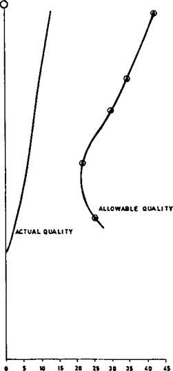
In order to analyze for DNB, one may compute the allowable steam quality at a given location in the evaporator with the actual quality. The system is considered safe if the allowable quality is higher than the actual quality. The allowable quality is based on the heat flux, pressure, mass velocity, and roughness and orientation of the tubes. Studies have been performed to arrive at these values. Figure 7.10 Shows a typical chart [14] that gives the allowable steam quality as a function of pressure and heat flux. It can be seen that as the pressure or heat flux increases, the allowable quality decreases. Another criterion for ensuring that a system is safe is that the actual heat flux on the steam side (inside tubes in water tube boilers and outside tubes in fire tube boilers) must be lower than the critical heat flux (CHF) for the particular conditions of pressure, flow, tube size, roughness, orientation, etc. CHF values are available in the literature; boiler manufacturers have developed their own CHF correlations based on their experience. See Chapter 8 for an example.
|
FIGURE 7.10 Allowable quality for nucleate boiling at 2700 psia, as a function of mass velocity and heat flux inside tubes. (From Ref. 14.) |
Compute the circulation ratio and check the system shown in Fig. 7.4 For DNB. A:
Figure 7.4 shows a boiler schematic operating on natural circulation principles.
The basis for estimating the flow through water walls is briefly as follows.
1. Assume a circulation ratio (CR) based on experience. For low pressure boilers (< 1000 psia), CR could be from 20 to 50. For high pressure boilers (1000-2700 psia), CR could range from 9 to 5. The following expression relates circulation ratio and dryness fraction, x:
CR =1 (36)
X
Hence, flow through the evaporator = CR x the steam generated.
2. Furnace thermal performance data such as efficiency, furnace exit temperature, and feedwater temperature entering the drum should be known before the start of this exercise, in addition to details such as the location of the drum, bends, size, and length of various circuits.
3. Mixture enthalpy entering downcomers is calculated as follows through an energy balance at the drum.
Hfw + CR xhe = hg + CR x hm (37)
4. As the flow enters the water walls, it gets heated, and boiling starts after a particular distance from the bottom of the furnace. This distance is called boiling height, and it increases as the subcooling increases. It is calculated as follows.
Hf — hm
Lb = L xCR x W^-f———— —
B Q
Beyond the boiling height, the two-phase flow situation begins.
5. Friction loss in various circuits such as downcomers, connecting headers, water wall tubes (single-phase, two-phase losses), riser pipes, and drums are calculated. Gravity losses, DPg, are estimated along with the acceleration losses, APa, in a boiling regime. The head available in the downcomer is calculated and equated with the losses. If they balance, the assumed CR is correct; otherwise, a revised trial is made until they balance. Flow through the water wall tubes is thus estimated.
6. Checks for DNB are made. Actual quality distribution along furnace height is known. Based on the heat flux distribution (Fig. 7.11), the
|
|
|
FIGURE 7.11 Typical heat absorption rates along furnace height. |
Allowable quality along the furnace height can be found. If the allowable quality exceeds actual quality, the design is satisfactory; otherwise, burnout possibilities exist, and efforts must be made to improve the flow through water wall tubes.
A coal-fired boiler has a furnace configuration as shown in Fig. 7.4. Following are the parameters obtained after performing preliminary thermal design:
Steam generated Pressure at drum
Feedwater temperature entering drum from economizer Furnace absorption Number and size of downcomers Number and size of water wall tubes Number and size of riser tubes Drum ID
Furnace projeced area
600,0 lb/h 2700 psia
570°F
320 x 106 Btu/h
4, 12 in. ID
416, 2lin. OD x 0.197 in. thick 15, 6 in. ID 54 in.
8400 ft2
Because it is difficult to estimate flow through parallel paths, let us assume that flow in each tube or circuit of downcomers, water walls, and risers may be near the average flow values. However, computer programs may be developed that take care of different circuits. The manual method gives a good idea of the solution procedure (though approximate).
Let circulation ratio CR = 8. Then x = 0.125. From the steam tables,
Tsat = 680°F hg = 1069.7 Btu/lb hf = 753.7 Btu/lb vf = 0.0303 cu ft/lb vg = 0.112 cu ft/lb hfw = 568 Btu/lb
Enthalpy of steam leaving water walls is
He = 0.125 x 1069.7 + 0.875 x 753.7 = 793.2 Btu/lb
Heat balance around the drum gives Steam flow = 600,000 lb/h
Water wall, downcomer flow = 8 x 600,000
= 4,800,000 lb/h
600,000 x 568 + 8 x 600,000 x 793.2 =
600,0 x 1069.7 + 8 x 600,000 hm
Hence, hm = 731 Btu/lb.
From the steam tables,
Vm = 0.0286 cuft/lb
Ve = 0.125 x 0.112 + 0.875 x 0.0303 = 0.0405 cu ft/lb
A. APg = head available = 106/(0.0286 x 144) = 25.7 psi.
B. APdc = losses in downcomer circuit.
The downcomer has one 90° bend and one entrance and exit loss. Using an approximate equivalent length of 7d,-,
Le = 104 + 16 + (7 x 12) = 204 ft The value f from Table 7.6 Is around 0.013.
8 x 600,000 x 0.0286 x 576 _ , „
= 3600 x »x 144 x 4 = 121 fps
0.013 x 204 x (12.1)2 x 12
DPdc =
2 x 32 x 12 x 0.0286 x 144 = 1.47 psi
C. Estimate boiling height:
753.7 — 731
Lb = 100 x 8 x 600,000 x ■
320 x 106 = 31 ft
Hence, up to a height of 31 ft, preheating of water occurs. Boiling occurs over a length of only 100 — 31 = 69 ft.
D. Gravity loss in boiling height:
0 .0286 + 0.0303
V m, mean specific volume =
= 0.02945 cu ft/lb
31
APg =———————- = 7.3 psi
G 0.02945 x 144 F
E. Friction loss in boiling height. Compute velocity through water wall tubes: d = 2.1 in.
_ 8 x 600,000 x 576 x 0.02945 w = 416 xp x (2.1)2 x 3600
= 3.93 fps
From Table 7.6, f = 0.019.
One exit loss, one 135° bend, and one 45° bend can be considered for computing an equivalent length. Le works out to about 45 ft.
A 0.019 x 45 x (3.93)2 x 12
W = 2 x 32 x 2.1 x 0.02945 x 144 = 0.28psi
F. Compute losses in two-phase flow, from Figs. 7.6-7.8, for x = 12.5% and P = 2700 psi,
R2 = 0.22, r3 = 1.15, r4 = 0.85
For computing two-phase losses:
APa = 1.664 x 10~n x tyr2G2
8
|
G = ^—’———— = 480,000 lb/ft2 h |
![]() X 600,000 x 576 416 x p x (2.1)
X 600,000 x 576 416 x p x (2.1)
AP„ = 1.66^ x 10_1^ 0.0303
X (4.8 x 105)2 x 0.22 = 0.026 psi Friction loss,
DPf = 4 x 10-10 x 0.0303 x °.°°19 f4
X 69 x (4.8 x 105)2 x 115 2:1
= 0.5 psi
6. 944 x 10 3 x 69 x 0.85
0.0303
|
|
Total two-phase loss = 0.026 + 0.5 + 13.4
= 13.926 psi, or 14.0 psi
G.
|
1.4 X ——■ x 0.0303 = 1.41 psi I A A x |
 Riser circuit losses. Use Thom’s method for two-phase unheated tubes. Let the total equivalent length, considering bends and inlet and exit losses, be 50 ft.
|
|
|
F = 1.4 (Fig. 7.9), f = 0.015 from Table 7.6 |
|
DPf = |
Note that in estimating pressure drop by Thom’s method for heated tubes, the Darcy friction factor was used. For unheated tubes, Moody’s friction factor could be used. Void fraction a0 from Fig. 7.12 = 0.36.
|
(38) |
![]()

|
0:112 |
![]()
|
1 |
![]() Dpg=[pf(1 — a1)+pga’] ^
Dpg=[pf(1 — a1)+pga’] ^
0:36
Total losses in riser circuit = 1.41 + 0.85 = 2.26psi.
H. Losses in drum. This is a negligible value; use 0.2psi. (Generally the supplier of the drums should furnish this figure.)
Total losses = b + d + e + f + g + h
= 1.47 + 7.3 + 0.28 + 14.0 + 2.26 + 0.2 = 25:51 psi Available head = a = 25.7 psi
Hence, because these two match, an assumed circulation ratio of 8 is reasonable. This is only an average value for the entire system. If one is interested in a detailed analysis, the circuits should be separated
|
FIGURE 7.12 Void fraction as a function of quality and pressure for steam [See Refs. 11, 16]. |
|
10 OJ A7 ^ ox A « ® u Ai O ai &2 os iu as u 07 M m i. o QUALITY |
 |
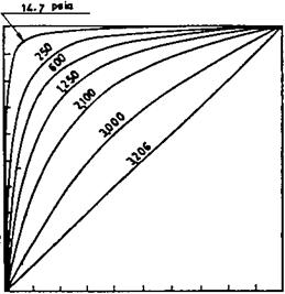
According to heat loadings, and a rigorous computer analysis balancing flows and pressure drop in each circuit can be carried out.
Typical furnace absorption profiles for the actual fuel fired are desirable for DNB analysis. These data are generally based on field tests, but for the problem at hand let us use Fig. 7.11, which gives typical absorption profiles for a boiler.
Furnace absorption 320 x 106
Average heat flux = —————— ————- = —
Furnace projected area 8400
= 38,095 Btu/ft2 h
There is a variation at any plan cross section of a boiler furnace between the maximum heat flux and the average heat flux, based on the burner location, burners in operation, excess air used, etc. This ratio between maximum and average could be 20-30%. Let us use 25%.
Again, the absorption profile along furnace height shows a peak at some distance above the burner where maximum heat release has occurred. It decreases as the products of combustion leave the furnace. The average for the entire profile
may be found, and the ratio of actual to average heat flux should be computed. For the sake of illustration, use the following ratios of actual to average heat flux at the locations mentioned.
|
Distance from bottom (ft) |
Ratio of actual to average heat flux |
|
40 |
1.4 |
|
56 |
1.6 |
|
70 |
1.0 |
|
80 |
0.9 |
|
100 |
0.4 |
We must determine the maximum inside heat flux at each of the locations and correct it for flux inside the tubes to check for DNB. Hence, considering the tube OD/ID ratio of 1.19 and the 25% nonuniformity at each furnace elevation, we have the following local maximum inside heat flux at the locations mentioned (q,- is taken as qp x d/d,-) :
|
Location (ft) |
Q, (Btu/ft2 h) |
|
40 |
1.4 x 38,095 x 1.25 x 1.19 = 79,335 |
|
56 |
90,440 |
|
70 |
56,525 |
|
80 |
50,872 |
|
100 |
22,600 |
It is desirable to obtain allowable quality of steam at each of these locations and check to be sure actual quality does not exceed it.
DNB tests based on particular tube profiles, roughness, and water quality as used in the operation give the most realistic data for checking furnace tube burnout. Correlations, though available in the literature, may give a completely wrong picture because they are based on tube size, heating pattern, water quality, and tube roughness that may not tally with actual operating conditions. However, they give the trend, which could be useful. For the sake of illustrating our example, let us use Fig. 7.10. This gives a good estimate only, because extrapolation must be carried out for the low heat flux in our case. We see the following trend at G, = 480,000 lb/ft2 h and 2700psia:
|
Location (ft) |
Allowable quality (%) |
|
40 |
25 |
|
56 |
22 |
|
70 |
30 |
|
80 |
34 |
|
100 |
42 |
Figure 7.13 Shows the actual quality (assuming linear variation, perhaps in reality quadratic) versus allowable quality. It shows that a large safety margin exists; hence, the design is safe. This exercise should be carried out at all loads (and for all circuits) before coming to a conclusion.
How is the circulation system analyzed in fire tube boilers?
The procedure is similar to that followed for water tube boilers in that the CR is assumed and the various losses are computed. If the losses associated with the assumed CR and the resulting mass flow are in balance with the available head, then the assumed CR is correct; otherwise another iteration is done. Because fire tube boilers in general use horizontal tubes, the allowable heat flux to avoid DNB is lower than when vertical tubes are used. With gas streams containing hydrogen and steam as in hydrogen plant waste heat boilers, the tube-side and hence the overall heat transfer coefficient and heat flux will be rather high compared to flue gas stream from combustion of fossil fuels. Typical allowable heat fluxes for horizontal tubes range from 100,000 to 150,000 Btu/ft2h.
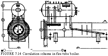
Perform the circulation calculations for the system shown in Fig. 7.14 with the following data:
Steam flow = 20,000 lb/h, steam pressure = 400 psig
Assume that saturated water enters the drum.
|
|
|

*
|
■O——————— “ ©■ FIGURE 7.14 Circulation scheme in fire tube boiler. |
 -©—I
-©—I
From steam tables, Vf = 0.194 and vg = 1.12 cu ft/lb. Assume there are two downcomers of size 4 in schedule 40 (di = 4.026 in.) and two risers of size 8 in schedule 40 (di = 7.981 in.). The total developed length of each downcomer is
22.5ft, and each has two 90° bends; the riser pipes have a total developed length of 5 ft. Exchanger diameter is 6 ft, and the center distance between the exchanger and the steam drum is 8 ft.
1. Assume CR = 15; then
Mixture volume = 0.067 x 1.12 + 0.933 x 0.0194 = 0.0931
The head available due to the column of saturated water is 11/(0.0194 x 144) = 3.94psi, where 11ft is the height of the water column.
2. ![]() Losses in downcomers:
Losses in downcomers:
A. Water velocity = 0.05 x
0.0194
(4.026)2
= 9 fps
Inlet plus exit losses = 1.5 velocity head
9
= 1.5 x 9 x
2 x 32 x 144 x 0.0194
0. 68 psi
B. Total developed length = 22.5 +2 x 10 = 42.5 ft, where 10 ft is the equivalent length of a 90° bend from Table 7.10.
( 202
APf = 3.36 x 0.0165 x I 15 x yJ
, 0 . 0194
X 42 . 5 x
(4.026)5
= 0 . 98 psi
Where 0.0165 is the friction factor. Equation (13) was used for pressure drop of single-phase flow.
Total downcomer losses = 0 . 68 + 0 . 98 = 1. 66 psi
3. Friction and acceleration losses in the exchanger may be neglected for this first trial, because in a fire tube boiler they will be negligible due to the low mass velocity.
4. Gravity losses in the exchanger: Using Fig. 7.7, r4 = 0.57.
0 57
DPg = 0.00695 x 6 x o = 1. 22 psi
5. Gravity loss in riser pipe:
5
Dpg = 0. 0931 x 144 = 0 37psi
6. Friction loss in riser:
20,000 0.0931
Velocity = 0 . 05 x 15 x————- I x———— 2 = 11 fps
1 2 ) (7 . 981)2
Inlet plus exit losses = 1. 5 x velocity head
1.
|
= 0 . 21 psi |
![]() 5x11x11
5x11x11
2 x 32 x 0.0931 x 144
20^ 2
Friction loss = 3. 36 x 0 . 014 x |^15 x —
|
X 5 x ^5 = 0 . 02 psi |
![]() 0.0931 (7 . 981)
0.0931 (7 . 981)
Where 5 ft is the developed length of the riser.
Let the losses in drum internals = 0.5 psi. This can vary depending on the type of internals used. Then
Total losses = 1.66 + 1.22 + 0.37 + 0.21 + 0.02 + 0.50 = 3.98 psi
This is close to the available head; hence CR = 15 is the circulation ratio for this system. The calculations can be fine-tuned with actual dimensions after the layout is done. One can compute the heat flux and compare it with the allowable heat flux to check if the circulation rate is adequate. Usually circulation is not a problem in this type of boiler, because the heat flux is low, on the order of 20,000-30,000 Btu/ft2h, whereas the allowable flux could be 100,000
150,0 Btu/ft2 h. See Chapter 8 for correlations for critical heat flux (CHF).
How is the flow in steam blowoff lines determined?
Whenever steam flows to the atmosphere from a high pressure vessel, the flow reaches critical flow conditions, and beyond a certain pressure further lowering of pressure does not increase the steam discharge. The flow is given by the equation
[17]
![]() (39)
(39)
The value of DP to be chosen depends on K, the system resistance, where
K =12 x
|
Where |
![]() D
D
Le = total equivalent length of all downstream piping including valves and fittings, ft f = Darcy friction factor d = pipe inner diameter, in.
Y = expansion factor (see Table 7.13) v = specific volume of steam before expansion, cu ft/lb DP = pressure drop, lower of actual upstream pressure minus downstream pressure or that obtained from Table 7.13
|
TAble 7.13 Limiting Factors for Sonic Velocity k = 1.3
|
Determine the flow of saturated steam from a vessel at 170 psia to the atmosphere if the total equivalent system resistance K = 10 and pipe inner diameter = 2.067 in.
Solution. Specific volume of steam at 170 psia = 2.674 ft3/lb. Actual DP = 170 — 14.7 = 155.3 psia. From Table 7.13, for K = 10, DP/P1 = 0.773, or DP = 170 x 0.773 = 131.5psia. Hence, use DP = 131.5psia. Also from Table
7.13 for K = 10, Y = 0.705. Hence
/ 1315 x 0 ‘ 5
W = 1891.0 x 0.705 x (2.067)2 x ‘ ‘
N 10 x 2 . 674
= 12,630 lb/h
7.34
Q:
How is the flow through boiler blowdown lines determined?
A:
Sizing of blowdown or drain lines is very important in boiler or process plant operations.
The problem of estimating the discharge rates from a boiler drum or vessel to the atmosphere or to a vessel at low pressures involves two-phase flow calculations and is a lengthy procedure [18].
Presented below is a simplified approach to the problem that can save considerable time for engineers who are involved in sizing or estimating discharge rates from boiler drums, vessels, or similar applications involving water.
Several advantages are claimed for these charts, including the following.
No reference to steam tables is required.
No trial-and-error procedure is involved.
Effect of friction can be easily studied.
Obtaining pipe size to discharge a desired rate of fluid, the reverse problem, is simple.
The basic Bernoulli’s equation can be written as follows for flow in a piping system:
|
|
1/2 |
|
2g |
|
V |
|
4 V2 v 104v dp H—— dk H— dv + dH = 0 2g g Substituting mass flow rate m = V/v: M2 / „ dv 4 dP dH — Idk + 2 — = -104 x——————— T 2g v v v2 Integrating between conditions 1 and 2: 1,2 dp |
|
2 |
|
V |
|
K + 2 ln —I = -10 |
|
DH |
|
2g |
|
M = |
|
K + 2 ln(u2/u1) |
|
X -104 |
 |
|
|
Where K = fl/d, the equivalent pipe resistance.
When the pressure of the vessel to which the blowdown pipe is connected is decreased, the flow rate increases until critical pressure is reached at the end of the pipe. Reducing the vessel pressure below critical pressure does not increase the flow rate.
If the vessel pressure is less than the critical pressure, critical flow conditions are reached and sonic flow results.
From thermodynamics, the sonic velocity can be shown to be
And
M=100/—«(§) s (44)
The term (dP/dv)s refers to the change in pressure-to-volume ratio at critical flow conditions at constant entropy.
Hence, in order to estimate mc, Eqs. (42) and (44) have to be solved. This is an iterative procedure. For the sake of simplicity, the term involving the height differences will be neglected. For high pressure systems the error in neglecting this term is marginal, on the order of 5%.
The problem is, then, given K and Ps, to estimate Pc and m. This is a trial — and-error procedure, and the steps are outlined below, followed by an example.
Figs. 7.16 And 7.17 Are two charts that can be used for quick sizing purposes.
1. Assume a value for Pc.
2. Calculate (dP/dv)s at Pc for constant-entropy conditions. The volume
Change corresponding to 2-3% of Pc can be calculated, and then (dP/dv)s can be obtained.
3. Calculate mc using Eq. (44).
4. Solve Eq. (42b) for m.
The term —10-4 Jj2 dP/v is computed as follows using Simpson’s rule:
2 dP r2
—
|
-104 |
![]()
|
P dP |
![]() = —104
= —104
1 v
P — P
■ s c x (Ps + 4 Pm + pc)
6
Where pm = density at a mean pressure of (Ps + Pc)/2.
The densities are computed as isenthalpic conditions. The term 2ln (v2/vj) = 2ln (ps/pc) is then found.
Then m is computed using Eq. (42b). If the m values computed using Eqs. (42b) and (44) tally, then the assumed Pc and the resultant mc are correct. Otherwise Pc has to be changed, and all steps have to be repeated until m and mc agree.
A boiler drum blowdown line is connected to a tank set at 8 atm. Drum pressure is 100 atm, and the resistance K of the blowdown line is 80. Estimate the critical mass flow rate mc and the critical pressure Pc.
The procedure will be detailed for an assumed pressure Pc of 40 atm.
For steam table Ps = 100 atm, s = 0.7983 kcal/kg °C; hl = 334kcal/kg, vl = 0.001445 m3/kg, or p = 692 kg/m3.
Let pc = 40 atm; then hl = 258.2 kcal/kg, hv = 669kcal/kg, Si = 0.6649, Sv = 1.4513, vl = 0.001249, vv = 0.05078.
Hence:
S — Si 0.7983 — 0.6649 X = Sv — Si = 1.4513 — 0.6649 = 0:1696
V = vl + x(vv — vl)
= 0.001249 + 0.1696 x (0.05078 — 0.001249)
= 0.009651 m3/kg
Again, compute v at 41 atm (2.5% more than Pc). Using steps similar to those described above, v = 0.0093 m3/kg.
Hence,
Mc = 100, /-.
9 TOC o "1-5" h z 8×1
= 100,/—————- = 16,733 kg/m2 s
|
0:0 |
![]() A/0.00965 — 0.0093 g/
A/0.00965 — 0.0093 g/
Compute the densities as
1 3
P — = 0001445 = 692 kg/m
The dryness fraction at 40 atm at isenthalphic condition is
334 — 258.2
X =——————- = 0.1845
669 — 258.2
Vc = 0.001249 + 0.1845 x (0.05078 — 0.001249)
= 0.010387 m3/kg pc = 96.3 kg/m3
Similarly, at Pm = (100 + 40)/2 = 70 atm,
Vm = 0.03785 m3/kg or pm = 264 kg/m3
2
|
-104 |
![]() DP 100 — 40
DP 100 — 40
X (692 + 4 x 264 + 96.3)
|
V |
![]() 6
6
= 184 x 106 x 2 x ln^
V1
= 2 x ln= 4.6 Pc
Substituting the various quantities into Eq. (42b),
2
|
/ |
![]() X 9.8
X 9.8
X 184 x 106
80 + 4.6 = 6530 kg/m2 s
The two values m and mc do not agree. Hence we have to repeat the calculations for another Pc.
This has been done for Pc = 30 and 15, and the results are presented in Fig. 7.15. At about 19atm, the two curves intersect, and the mass flow rate is about 7000kg/m2 s. However, one may do the calculations at this pressure and check.
As seen above, the procedure is lengthy and tedious, and trial and error is involved. Also, reference to steam tables makes it cumbersome. Hence with various K values and initial pressure Ps, a calculator was used to solve for Pc and m, and the results are presented in Figs. 7.16 And 7.17.
|
|
|
FIGURE 7.16 Solving for m. |
|
|
What is the effect of stack height on friction loss and draft?
Whenever hot flue gases flow in a vertical stack, a natural draft is created owing to the difference in density between the low density flue gases and ambient air, which has a higher density. However, due to the friction losses in the stack, this available draft is reduced.
If 100,000 lb/h of flue gases at 400°F flow in a 48 in. ID stack of 50 ft height, determine the net stack effect. Ambient air temperature is 70°F.
Solution. Density of flue gases (see Q5.02) at 400°F = 39.5/860 = 0.0459 lb/cu ft. Density of air at 70°F = 40/530 = 0.0755 lb/cu ft. Hence
Total draft available = (0.0755 — 0.0459) x 50 = 1.48 lb/ft2
12
= (0.0755 — 0.0459) x 50 x——-
62:4
= 0.285 in. WC
(The factor 62.4 is density of water, and 12 converts ft to in.)
Let us see how much the friction loss per unit length is. From Eq. (26),
Ј i v
DP = 93 x 10—6 x f x W x — r
D5
V = 1/0.0459 = 21.79 cu ft/lb. To estimate the friction factor f, we need the
Reynolds number. From the Appendix, m = 0.058 lb/ft h. Hence
100,000
Re = 15.2 x——— ,——- = 546,000
|
0.316 (546,000)° |
![]() 48 x 0.058
48 x 0.058
F = ^=25 = 0.012
21:79
D P = 93 x 10—6 x 0.012 x (100,000)2 x 50 x —
485
= 0.048 in. WC
Hence
Net draft available = 0.285 — 0.048 = 0.237 in. WC
Discuss the flow instability problem in boiler evaporators.
In once-through boilers or evaporators generating steam at high quality, the problem of flow instability is often a concern. This is due to the nature of the two — phase pressure drop characteristics inside tubes, which can have a negative slope with respect to flow under certain conditions. The problem is felt when multiple streams are connected to common header systems as in once-through or forced circulation systems. Small perturbations can cause large changes in flow through a few tubes, resulting in possible dryout or overheating conditions. Vibration can also occur. The problem has been observed in a few low pressure systems generating steam at high quality.
To illustrate the problem, let us take up the example of steam generation inside a tube. For the sake of analysis, a few assumptions will be made:
Heat flux is uniform along the length of the tube,
Steam at the exit of the tube has a quality x,
Some subcooling of feedwater is present. That is, the feedwater enters the boiler at less than the saturation temperature.
We are considering a long straight tube without bends to describe the nature of the problem.
If a tube is supplied with subcooled water, the boiling starts after the enthalpy of the water has risen to the saturated liquid level. Thus the length of the boiler can be divided into two portions, the economizer portion and the evaporator, their lengths being determined by the heat input to their respective sections.
Let W be the flow of water entering in lb/h. Let Q = total heat input to the evaporator and Q/ the heat input per unit length, Btu/ft h. The steam quality at the exit of the evaporator is x, fraction. Let the economizer length be L1 ft. The pressure drop APj in the economizer section is
A Pj = 3.36/ L1 W2vf /d5 (45)
Where
L = WAh/Q/ (46)
Ah = enthalpy absorbed by water in the economizer portion, Btu/lb v/ = average specific volume of water in the economizer, ft3/lb
In Eq. (46) we are simply using the fact that heat addition is uniform along the tube length.
D, = tube inner diameter, in.
The pressure drop in the evaporator region of length L — L1 is given by
|
,, vf +x(vg — vf)/2 DP2 = 3.36f(L — LOW2 fV g5 f>’ (47) |
![]() V
V
D5
Now
Xhfg _ L — Lj
Dh — Lx (48)
Because the heat applied is uniform along the evaporator length, and we are simply taking the ratio of energy absorbed in the evaporator and economizer, which is proportional to their lengths.
Hfg = latent heat of vaporization, Btu/lb
Vg, Vf = specific volume of saturated liquid and vapor, ft3/lb
Now substituting for x from Eq. (48) in. to Eq. (47) and for L1 from Eq. (46) and simplifying the above equations, we can obtain the total pressure drop as follows.
DP = DP 1 + DP2
, . Vg — Vf — I Vg — Vf n Vg — Vf
= kW Dh f — kW21 Dh f — Vf + kWL2Qr
2Qlhfg hfg / 2hfg
(49)
Or
DP = AW3 — BW2 + CW (50)
Though this is a simplistic analysis for two-phase flow pressure drop, it may be
Used to show the effect of the variables on the process.
Equation (50) is shown in Fig. 7.18. It is seen that the curve of pressure drop versus flow is not monotonic but has a negative slope. This is more so if the steam pressure is low. Hence it may lead to unstable conditions. For example, at the pressure drop condition shown by the horizontal line, there could be three possible operating points, which may cause oscillations and large variations in flow through the circuit. This is likely if multiple streams are connected between headers, where a few tubes can receive very small flows, causing tube overheating concerns and possible DNB conditions.
To improve the situation, one may add a restriction such as a control valve or orifice at the inlet to the economizer section. The orifice increases the resistance in proportion to the square of the flow as shown by the term R in Eq. (51). Figure 7.18a also shows the effect of the orifice, which makes the pressure drop curve monotonic.
DP = AW3 +(R — B)W2 + CW (51)
|
FIGURE 7.18 Effect of (a) orifice size, (b) pressure, and (c) inlet subcooling on the stability of two-phase boiling circuits. |
|
(b) |
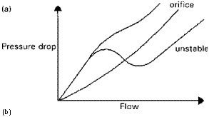
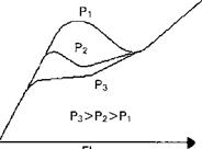
|
Pressure drop |
![]() Because the ratio of specific volumes of steam and water is much larger at low steam pressures and the latent heat is also large, the problem is more likely at low pressures than at high pressures, as indicated in Fig 7.18b. Decreasing the inlet subcooling by using a higher feedwater temperature also helps as shown in
Because the ratio of specific volumes of steam and water is much larger at low steam pressures and the latent heat is also large, the problem is more likely at low pressures than at high pressures, as indicated in Fig 7.18b. Decreasing the inlet subcooling by using a higher feedwater temperature also helps as shown in
Fig. 7.18c. If inlet subcooling is eliminated, Dh = 0 and then Eq. (50) becomes more stable as shown by the equation
DP = BW2 + CW (52)
|
NOMENCLATURE |
|
|
A |
Area of orifice, in.2 |
|
C |
A constant depending on ratio of gas specific heats |
|
CR |
Circulation ratio |
|
Cd |
Discharge coefficient |
|
Cv |
Control valve coefficient |
|
D |
Tube or pipe outer diameter, in. |
|
Dg, di |
Orifice diameter and pipe or duct inner diameter, in. |
|
E |
Expansion factor for fuel oils |
|
F |
Friction factor |
|
G |
Gas mass velocity, lb/ft2 h |
|
H |
Differential pressure across flow meter, in. WC |
|
K |
Enthalpy of mixture at exit, Btu/lb |
|
Hf ’ hg’ hm ’ hfw |
Enthalpy of saturated liquid, saturated steam, mixture, and feedwater, Btu/lb |
|
K |
System resistance |
|
Km |
Valve recovery coefficient |
|
Ksh |
Superheat correction factor |
|
L |
Length of pipe, ft |
|
Le |
Equivalent length, ft |
|
M |
Constant used in Q7.25 |
|
Mc |
Mass flow at critical condition, kg/m2 s |
|
MW |
Molecular weight of gas or vapor |
|
Nh |
Number of rows deep in a tube bundle |
|
Pa |
Accumulated inlet pressure, psia |
|
Pb |
Backpressure, psig |
|
Ps |
Set pressure, psig |
|
Pv |
Vapor pressure, psia |
|
Pi, P2 |
Inlet and exit pressures, psia |
|
DP |
Pressure drop, psi |
|
DPg |
Gas pressure drop, in. WC |
|
DPa, DPf, DPg |
Acceleration loss, friction loss, and loss due to gravity, psi |
|
Q |
Fluid flow, gpm |
|
Re |
Reynolds number |
|
R2; r3; r4; rf |
Factors used in two-phase pressure drop calculation |
|
S |
Entropy |
|
S |
Specific gravity of fluid |
|
St, Sl |
Transverse and longitudinal pitch, in. |
|
T, T |
Fluid temperature, °F or °R |
|
Ts |
Saturation temperature, °F |
|
V |
Specific volume of fluid, cu ft/lb |
|
Vc |
Critical velocity, m/s |
|
V |
Fluid velocity, ft/s |
|
Vf; vg; vm |
Specific volume of saturated liquid, steam, and mixture, cu ft/lb |
|
W |
Flow, lb/h |
|
X |
Steam quality, fraction |
|
Y |
Volume fraction of gas |
|
Y |
Expansion factor |
|
B |
Do/dt ratio |
|
M |
Fluid viscosity, lb/ft h |
|
P |
Density of fluid, lb/cu ft; subscript g stands for gas |
|
M |
Specific volume of fluid, m3/kg |


 12 августа, 2013
  doctype
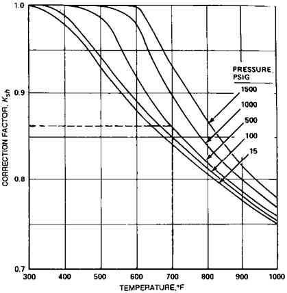
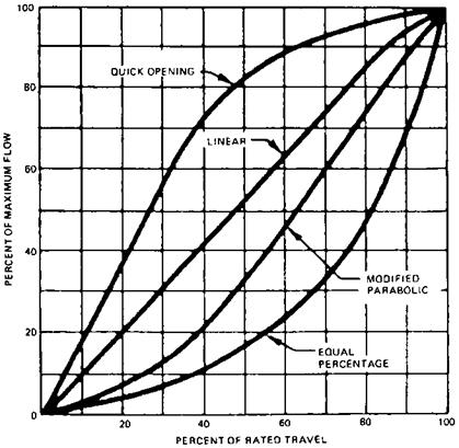

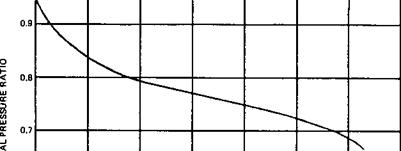
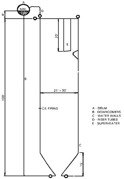
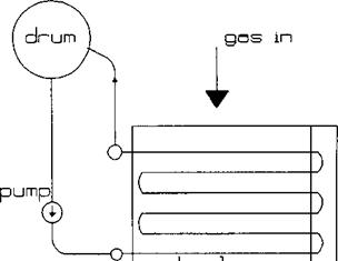
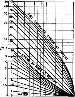
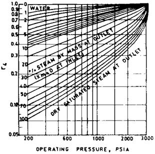
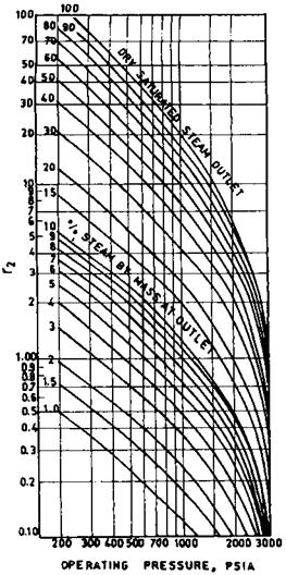
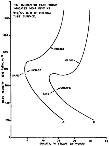
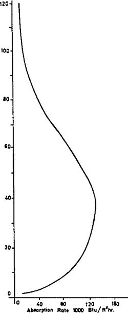
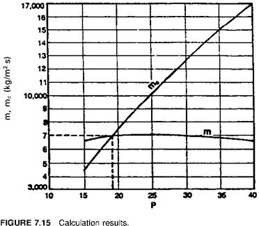
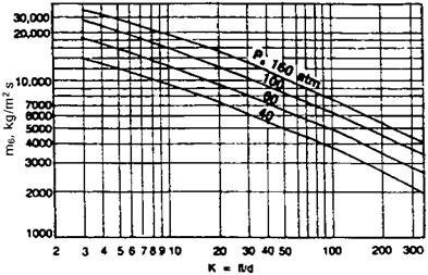
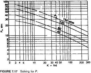
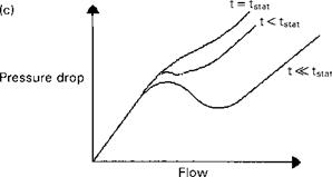
 Опубликовано в рубрике