This method of dust collection uses the property of dust particles to acquire electrical charge, when subjected to high DC voltage.
An ESP is a large settling chamber in which discharge or emitting electrodes (EEs) and collecting electrodes (CEs) are suspended from the roof with high-voltage DC power (by transformer-rectifier [TR] sets) impressed on them and charging them with positive and negative polarities, respectively. The high voltage accelerates some free electrons present in the gas. The free electrons then collide with the gas molecules with such a force that they strip the molecules of an electron. The electrons then flow toward the positive collecting plate and the positively charged gas ions toward the negative discharge electrode. The stream of electrons collides with the gas and dust particles that are travelling slowly in the ESP casing and charges them negatively, making them flow toward the collecting plates. On reaching the collecting plate, the dust loses charge and settles on the collecting plate, which is dedusted periodically by the rapping system. Some positively charged particles are collected on the EEs. Figure 8.32 depicts this action.
|
Collecting plate FIGURE 8.32 Particle collection in an electrostatic precipitator. |
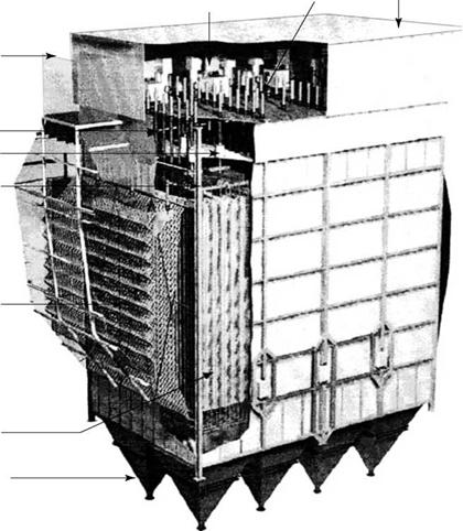
ESP is a complete system (Figure 8.33) consisting of
• Mechanical equipment:
• Housing with inlet and outlet funnels and perforated inlet screen
• Ash hoppers with electrical heating pads
• Supporting structure with proper expansion arrangements
• Electrode assemblies with supporting system and insulators
• Rapping system, mechanical or magnetic
• Insulation and lagging
• Electrical system:
• TR sets on the roof
• Cabling from local motor control center (MCC) to TR sets
• Control system
• ESP housing is a large sturdy chamber capable of withstanding all the weights and
Forces imposed.
• It is an airtight chamber of carbon steel (CS) sheet of 5 or 6 mm thickness, with adequate stiffening for maintaining the straightness of sides. Usually a steel sheet of A-36 specification is adequate, as the flue gases are not corrosive and are sufficiently cool.
• All electrodes are housed in the casing and are suspended from the top.
• The internals are separated by adequate walkways inside the enclosure.
• The cross section has to be large enough to slow the gases to permit sufficient treatment time.
• It is absolutely essential to have gases filling the entire chamber for proper collection, for which a carefully designed perforated screen as a minimum (along with inlet flow distribution devices in many cases) is installed at the inlet end. Turning vanes and flow straighteners are also installed as required.
|
|
|
Inlet duct |
|
Penthouse Support Insulator High-voltage Frame |
|
Perforated Plates |
|
TR sets |
|
Rapper |
|
Weather Enclosure |
|
Collecting and discharge electrodes |
|
Hopper |
|
FIGURE 8.33 Arrangement of dry electrostatic precipitator with top rapping. (From Hamon Research-Cottrell, U. S.A. With permission.) |
• The shape of the inlet and outlet funnels is also very important for an even gas flow. Flow modeling by computer can optimize the casing design, replacing the Perspex models of the past.
• An aspect ratio (width of total ESP versus height of electrodes) of ~1:1.2-1.4 is considered an economical and good design.
• The casing is externally insulated and clad for human comfort as well as prevention of condensation.
• Ash hopper design is very important. The slope and size of ash hoppers is important for optimal functioning. The hoppers for coal ash are built with a minimum valley angle of 55° or side slopes exceeding 60° for smooth sliding of ash. Heating pads are essential to keep the hoppers hot, as fly ash is highly hygroscopic, creating hopper jamming even after a few hours of stoppage. Many times hopper storage of 8 h is demanded to permit shift operation of the ESP with electrical system
Fault. With inadequate hoppers, the first ones tend to overfill and spill over, creating short circuiting of electrodes and stoppage of the entire unit. The hoppers must terminate at an elevation of —2-2.5 m above ground level to permit installation of rotary valves and ash disposal units below. Vibrators, level monitors, and poke holes are also required.
• Supporting structure takes on the weight of the entire ESP casing with all internal and external mountings and the hoppers with ash. The casing has to be anchored at the front, rear, or middle and allowed to expand with respect to the fixed structure over special roller bearings. Expansion joints at the ends of front and rear funnels in the gas ducting are necessary to connect to upstream and downstream ducting.
• Electrodes, both the EE and the CE, are suspended from the top and charged with negative and positive polarities, respectively. The EEs are connected to the TR set terminals by suitable conductors with ceramic insulators. The CEs are grounded.
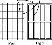
•  Emitting electrodes. On the basis of the type of EE, an ESP is classified as the weighted wire, rigid, or rigid frame type. All three types are depicted in Figure 8.34. Emitting electrodes need to extend beyond the zone covered by the accumulated ash.
|
Rigid frame Discharge Electrode
Assembly Frame |
Structural
Tube
R
Corona
Studs
|
Special Shapes |
|
Weighted Wire Electrode types |
|
||
FIGURE 8.34
Types of emitting electrodes. (From Power magazine. With permission.)
• In weighted wire design, a thin (typically 3 mm) ss wire is made into a spring form with a weight attached at the bottom for maintaining straightness.
• A rigid electrode is a heavy-rolled section provided with spikes.
• A rigid frame is a tubular frame with electrode wires fixed vertically.
The weighted wire design is light in weight and good in performance but has shorter life, as the springs tend to break as the electrode lengths exceed —9 m (—30 ft). The disturbing aspect of wire breakage is not so much about the performance loss but a possibility of the attendant short circuiting, calling for an immediate repair. The rigid electrode and rigid frame designs rely on heavier members for stronger construction and reliability. Large ESPs for utilities are made with pipe — or special-shaped heavy electrodes or rigid frames. The weight of an ESP increases but the reliability also improves significantly.
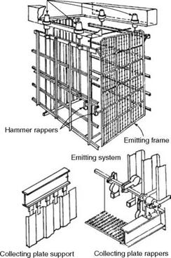
• Collecting electrodes are cold-rolled steel sheets of —600 mm (24 in.) width or more, rolled to special shapes for effective collection of ash. Ash collects on the entire height of the plate and, when dislodged, falls in layers. The height of the collecting plates is one of the prime dimensions of an ESP. Plates as tall as —15 m (—50 ft) are employed on large ESPs. Plate thickness varies from —1.0 to 1.5 mm. The straightness is very important for proper performance, and besides the crimping of the sheets, stiffeners may also be welded to avoid waviness. In Figure 8.35, a typical collecting plate and its supporting arrangement are shown.
|
Four-point support
FIGURE 8.35 Electrodes and side rapping system. (From Power magazine. With permission.) |
• Rapping is a periodic shaking of the electrodes to dislodge the accumulated dust. The dust accumulated on the collecting plates tends to agglomerate and, when rapped, dislodges and falls in several layers. From discharge electrodes, a small amount of dust is collected. Each electrode needs rapping separately for an effective ash removal, and the sequence has to be in the direction of the gas flow.
Rapping force has to be carefully selected, as a heavy bang is likely to drop a lot of dust, leading to a rebound and reentry of dust into the gas stream, whereas a gentle tap is unlikely to dislodge the dust from the electrodes effectively. The rapping force and frequency have to be different from the top to the bottom of the electrode and from the front to the rear of the ESP.
Mechanical rapping, which is still the most popular form, involves hitting the electrodes at the top, middle, or bottom. The tumbling hammers drop with free fall and the acceleration so caused sends shock waves, loosening and dropping the dust. High-resistivity fly ash is particularly difficult to collect, and a rapping force caused by an acceleration of minimum 100 g is required. Rapping the collecting plate from the bottom is depicted in Figure 8.35. The hammers of varying weights are connected to a slowly rotating shaft driven from outside and hit the electrodes in a predetermined manner.
Rapping of EEs is also required, but fewer rappers are needed because the ash collection is low. Mechanical rapping from the tops of electrodes is also a popular method. Magnetic impulse rapping is another method. The hammers are dispensed with, and magnetic waves are used for vibrating the electrodes.
• A field in an ESP is a section complete with its own TR set. The DC voltage generated in TR sets has been steadily increasing along with the spacing between the electrodes. Prior to mid-1980s, the spacing was —225 to 250 mm (9-10 in.) with voltage levels of <50 kV on an average. These voltage levels have recently reached 85 kV and more. This rise has helped in widening the collecting plate spacing to 300 and 400 mm, which reduces the plate requirement and offers better access. The limit for higher voltage is set by the tendency for arcing between the electrodes.
• Control systems create and maintain an electrical field to facilitate dust collection. They also minimize power consumption consistent with performance. The control system maximizes the effective voltage and current. When sparks and arcs can damage the internals, the control system reduces the power to the affected field. Typically, for each 2500 m2, a separate bus section is provided.
• With stringent pollution norms, it is usual to have a minimum of three fields in an ESP, although single-field units have been employed with nearly 90% collection efficiency. With three fields, the efficiency is >99%. In large utility boilers, firing high-ash coal, it is not unusual to have six or seven fields to meet —30 mg/N m3 levels with collection efficiencies >99.9%. With low-ash coals, it is possible to achieve particulate emission levels as low as —10 mg/N m3. It is usual to specify that an ESP should deliver the required performance even with one field out of service.
• The maximum collection of ash is in the first field where nearly 80% takes place. Normally, each field of the ESP collects —80% of the incoming dust load. In large ESPs, the difference in ash collection between the first and the last set of hoppers can be as high as 100 times.
The ash handling system should be designed for heavy loads in the first field, and in the second field when the first one fails. The collection in the subsequent fields progressively
Reduces, but the particles are finer. The ash handling plant should be designed such great variations in mind.
An ESP is the most popular particulate collection system in all sizes of boilers based on its enormous advantages:
• Collection efficiencies >99.9% can be achieved effortlessly by increasing the fields. The exit dust load can be as low as —30 mg/N m3 with high-ash coals and even 10 mg/N m3 for low-ash coals.
• Electrostatic precipitators can be effective in collecting not only the coarse particles but also the fine particles and fumes. They can collect a wide range of dust, from submicron levels of 0.05 |jm to large particles of 10 |jm or more.
• The pressure drop is surprisingly low, between 20 and 30 mm wg, not much higher than that for a settling chamber because the internals are wide apart and the gas velocity is low. More importantly, the dust is worked upon and not the flue gases, unlike in the cyclones or bag filters.
• The power consumption is very low for the same reason.
• Because of the low gas velocities, the erosion of the internals is not an issue. EPS is ideally suited for coals with high amounts of abrasive ash.
• ESP is an extremely reliable and rugged system, which requires practically no maintenance.
• An ESP is expensive, particularly in lower sizes on a specific cost basis because of the numerous components.
• It occupies a lot of floor space.
• Emission limits are exceeded during upset conditions such as soot blowing. If the emission limits are to be observed under all conditions, the ESP becomes too large.
• For very low emission limits such as 30 mg/N m3 from high-ash coal-fired boilers, bag filters become attractive, if the ash is not too abrasive.
• The collection efficiency of particles of 2 |jm and below is poor.
The classical Deutsche-Anderson equation describes the behavior of an ESP reasonably well, although it is deficient in predicting the performance.
Collection efficiency of an ESP can be defined as
|
Outlet dust inlet dust |
![]() „ (inlet dust — outlet dust)
„ (inlet dust — outlet dust)
|
(8.13) |
![]() E = ————————————————- 1 or 1
E = ————————————————- 1 or 1
Inlet dust
An ESP is a percentage collector. Outlet dust loading increases in proportion to the inlet dust loading, and if the outlet concentration is to be maintained at high dust loads, the ESP
Size has to be increased. This is an important point of difference compared with the FFs in which the outlet loading remains indifferent to the inlet load.
Collection efficiency E(%) = 1 — e—Aw/V (8.14)
Where
A = the area of CEs in square meters
V = actual gas volume in cubic meters per second w = migration or drift velocity in meters per second e = natural logarithm 2.718
Collection efficiency is a function of
1. A/V, the specific collection area (SCA) in square meters per cubic meter per second of flue gas. More collection area improves collection efficiency for the same gas volume.
2. w, the migration velocity, is governed by ash resistivity. Higher migration velocity means better collection efficiency. Lower ash resistivity promotes higher migration velocity.
Uniform gas flow distribution is of paramount importance in achieving the predicted collection.
Collecting area A (m2) = V[e1/(1—E)]
W
Collecting area is directly proportional to the gas volume and inversely to the migration velocity. It is the total area of the collecting plates measured on both sides. SCA is the way by which the ESP sizing is understood and compared for various fuels and resistivities.
SCA comparison for ESPs can be done only after they are rationalized for the electrode spacing. It is usual to convert the SCA for 300 mm electrode spacing, an informal industry standard. Since there are a number of variables in the sizing of ESP and most of them are difficult to measure accurately, the ESP sizing is largely empirical and is based on the previous data.
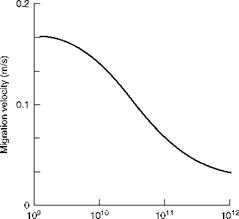
• Migration or drift velocity is the theoretical average velocity of the charged par — tides as they move toward the CEs. Higher migration velocity means lower collection surface and smaller ESP. This is dependent on how easily the dust particles acquire charge when subjected to a high voltage, that is, how low is the ash resistivity (measured in ohm centimeters). As the ash resistivity increases, the migration velocity reduces, as shown in Figure 8.36. Fuel and ash characteristics, operating temperature, voltage levels, and gas flow distribution affect migration velocity.
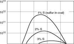
• Ash resistivity values typically vary from 108 to 1014 O cm, with 5 X 10⁹-5 X 10¹⁰ O cm as the ideal range for ESPs. Ash resistivity of >5 X 10¹¹ O cm poses difficulty in collection, whereas resistivity of <109 O cm leads to ash re-entrainment issues. Such low resistivity in ash is rare, but, on the higher side, 2 X 10¹² O cm is possible, with low-sulfur coals and a rather large ESP. Peak ash resistivity occurs at
|
Ash resistivity (Q cm) |
|
100 150 200 Temperature (°C) |
|
FIGURE 8.36 Ash resistivity versus migration velocity. |
![]() FIGURE 8.37
FIGURE 8.37
Variation of resistivity with sulfur and temperature.
120-220°C, depending on the ash and coal characteristics, as shown in Figure 8.37. At higher temperatures, the resistivity is inversely proportional to the absolute gas temperature, whereas at lower temperatures, it is directly proportional to the absolute temperature.
• Fuel ash constituents that reduce the resistivity and collection surface are H2O and S. Ash constituents such as Na and K and unburnt carbon also reduce the resistivity.
Ca, Mg, Al2O3, and SiO2, however have the opposite effect. Al2O3 and SiO2 are basically electrical insulators and do not acquire electrical charges. This understanding is very important to predict how the ESP would behave with different fuels or how a change of fuel would affect the ESP behavior.
• Hot ESPs, which are placed ahead of AHs in some installations, are built based on ash resistivity at higher temperatures. Since the results have not been encouraging, the hot ESP concept has been abandoned.
• Gas velocity ranges from 1 to 2 m/s and is required to be in the lower end for both high and low ash resistivities. High-resistivity ash requires more time for collection, whereas low-resistivity ash has tendencies to re-entrain. Approximately 1.3 m/s gas velocity is optimum for coal firing. Greater gas velocity reduces the ESP cross section with a possibility of undersizing. At the same time, a very low velocity could result in meandering of gases with a possibility of ionization, leading to sparkover and performance degradation.
• Treatment time is the time when gases reside inside the ESP from the first to the last electrode. For high-resistivity ash, it varies from 15 to 25 s, whereas for medium — resistivity ash, it varies from 7 to 10 s.
• Fly ash conditioning is sometimes required for collecting dust. SO3 is the most popular agent, which is introduced at the inlet in trace amounts. This helps to reduce the ash resistivity and improve collection. NH3 is, at times, introduced because it helps agglomerate particles, which prevents re-entrainment. As much as 20-30% reduction in ESP size is possible by gas conditioning.
The most extensive use of ESPs is in coal-fired boilers of all sizes. Collection efficiencies exceeding 99.9% are common to give outlet emissions of <30 mg/N m3 at 6% O2.
Electrostatic precipitators are also employed in boilers firing bagasse, wood, bark, oil, and municipal refuse. The resistivity of ash in all cases is less than coal mainly because the moisture content in fuel helps to lower it. SCA in these ESPs is considerably lower, leading to smaller unit sizes.
|
O |
|
Normal Pulse Operation operation |
|
— -<— Tube Normal Reverse gas sheet operation operation |
|
(b) |
|
|
|
|
 |
|
 |
|
|
|
|
|
|
|
|
![]()
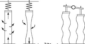
The bag cleaning is gentle. The section that needs cleaning is isolated, and the flow of the cleaned flue gas is reversed to make the bags shrivel, causing the dust to fall off the dirty bags. The PJF design is exactly the opposite of the RGF design. The bags are open from the top, and the dust is collected on the outside of the bags and periodically blown with high-pressure air. As the air pulses travel along the bag length, the bags expand intermittently, loosening and shaking off the dust. PJFs require stronger bags. They were used in smaller sizes for industrial applications for gas volumes of 50 Am[8]/s. For utilities, RGFs were common but PJFs are also finding their way into utility markets due to their improved designs and bags.
• The installation costs of FFs are lower than those of ESPs.
• Fabric filters are more compact and occupy less floor space.
• Very high collection efficiency of >99.9% can be achieved very easily and economically. Outlet loadings as low as 10 mg/N m3 at 6% O2 are achievable.
• The outlet concentration remains practically constant irrespective of the variation of the inlet loading.
• Fabric filter performance is not concerned with the resistivity of ash or sulfur in coal. For such conditions, FFs are smaller and cheaper than ESPs.
• Collection of very fine particles of <2 |jm is possible.
• With bio, wood, and allied fuels, the moisture in fuel tends to agglomerate the dust cake on the bags into a porous sieve, aiding dust collection and reducing the size
Of FF.
• SO2 in flue gas can be absorbed by the dust cake if it is alkaline.
• Bag replacement at 20-40% of the initial cost is needed every 2-3 years, depending on how abrasive the ash is.
• Pressure drop can be as high as 150-200 mm wg leading to substantial auxiliary power consumption.
• Bag materials cannot withstand erosive ash for long periods.
• As bio fuels wood, and allied fuels are light, the burning carbon particles get carried away until intercepted by the bags of FF that pose a serious fire hazard.
Electrostatic precipitators are still preferred due to low operating power costs, low maintenance, and exemplary availability despite higher installation costs, poorer collection of very fine dust (<2 |jm), and larger floor space. However, FFs have been gaining ground:
• Despite their higher power and bag replacement costs.
• Dust collection efficiency is uniformly high at all loads with all sizes, FFs require less floor space, and exhibit dust cake properties that often help in dry acid gas removal.
The pollution laws are gradually demanding very low emissions of <30 mg/N m3 and lower opacity standards, which favor FF over ESP. Also for low-sulfur coals with high ash resistivity, the ESP size makes FF more economical when such low emissions are to be achieved.
Performance depends on the following parameters:
• Air to cloth ratio (A/C)
• Gas pressure drop
• Fabric life and cleanability
• Fabric, dust cake, and gas properties
• A/C ratio expressed in terms of actual gas flow per unit cloth surface in Am3/m2h (Aft3/ft2/h) is perhaps the most important parameter for sizing the filter. A higher ratio requires a smaller FF. A greater gas pressure drop means more cloth wear. Bag cleaning and replacement are required more frequently. Selecting an optimum A/C ratio requires a balance of initial costs, running costs, and performance.
• A/C ratio is also called the filtration velocity and expressed in terms of meters per minute or feet per meter.
• A/C ratio is expressed as gross, net, or net-net in increasing value, depending on whether it includes
• Total cloth area of all bags in FF
• Area of bags under cleaning deducted from the total area
• Area of bags under maintenance deducted from the total area
It is the practice in the industry to express the A/C ratio on a net basis. Typical filtration velocities for coal firing on a net basis are as follows:
RFG: 0.45-0.7 m/min or 27-42 m/h
(1.5-2.3 ft/min) (90-140 ft/h)
PJF: 0.9-1.2 m/min or 54-72 m/h
(3-4 ft/m) (180-240 ft/h)
• Gas pressure drop in an FF gradually builds up until it reaches a set point when the bags are dedusted. Pressure drop is 150-200 mm wg from flange to flange across the bag, dust cake, and bag attachment to tube sheet.
• Fabric life depends on the type of FF and the cleaning forces. Fabric suitabilities vary for each application.
• Dust cake properties are important for optimum cleaning. A porous and softly adherent dust cake acts as a sieve to trap the dust. Therefore, care is needed to retain an optimum thickness of dust cake on top of the fabric after each cleaning.
As mentioned earlier in Sections 8.6.1 and 8.6.3, an alkaline dust cake helps to reduce dry acid emissions.
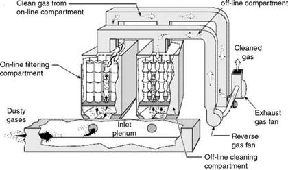
The flue gas enters the RGF near the bottom plate and passes through the inner sides of the bags, which are open at the bottom and closed at the top, depositing the dust on the insides. The bags are held between the top and the bottom plates. The clean gases leave at the top plate. Bags are grouped together to make a section or compartment, which is taken up for on-load cleaning or maintenance during which two sections are taken out of service. The cleaned gases are made to flow back through a section, making the bags bend inward to drop the ash. The cleaning operation is gentle allowing longer life of the bag and permitting the usage of woven material. The bags are typically 200-300 mm in diameter and 7-11 m long and A/C ratios of —40 m3/m2 h (on net-net condition). The cleaning gas flow varies from 28 to 35 m3/m2 h, and the operation is designed to clean only one section at a time. The gas flow in active sections naturally increases as the total gas flow remains the same (Figure 8.39).
|
FIGURE 8.39 Reverse gas filter. |
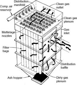
![]() The flue gas enters the PJF at the bottom and passes through the outer sides of the bags, which are closed at the bottom and open at the top, depositing the dust on the outsides.
The flue gas enters the PJF at the bottom and passes through the outer sides of the bags, which are closed at the bottom and open at the top, depositing the dust on the outsides.
|
Reverse gas to
|
|
FIGURE 8.40 Pulse jet filter. (From Power magazine. With permission.) |
The cleaned gases flow from the top toward the exit. Periodically, the gases are cleaned by blowing fresh air through the bags at high pressure, which expands the bags and allows them to shed the dust from their outsides. The cleaning forces are heavier, demanding use of expensive felted material and strong support cages. In PJFs, the bags are smaller, —130 to 150 mm in diameter, and shorter, —5 to 8 m long; A/C ratio is higher at —70 m3/m2 h (Figure 8.40).
Higher A/C ratio, on-load cleaning facility, and no internal walkways make the PJF smaller. There can be as much as 50% reduction in the plan area, making the installed costs lower by —20%. The woven bags in RGF are cheaper and have longer life, thereby reducing the operating costs.
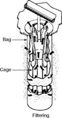
Bags constitute the heart of the FF system, as the performance, life, and availability are dependent on the material, construction, and supporting system of the bags. Woven fiberglass bags are most commonly used for coal application. Bag life is affected by (1) flexing action on the bag during cleaning and (2) bag binding due to trapping of small particulate matter in the pores. The latter causes an excessive pressure drop, requiring an early replacement. In RGFs and SFs, the bags are fastened at the bottom to a thimble in the tube sheet. At the top, a metal cap is sewn. In RGFs, the bags are supported with springs (Figure 8.41).
Besides fiberglass, synthetic patented materials such as Nomex, Ryton, Daytex, Teflon, and so on, are used depending on the ash properties.
|
|
|
Mode |
|
FIGURE 8.41 Bags of pulse jet filter. (From Power magazine. With permission.) |


 29 августа, 2013
  admin
admin 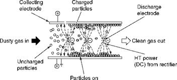
 Опубликовано в рубрике